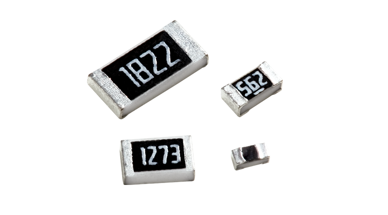
Even if the specifications fully cover the circuit power requirements, overheating, excessive temperature drift, blackening, and even catastrophic failure may occur during mass production —— this is a common pitfall for power, industrial control, and drive engineers.
Many people first suspect the quality of the component, but in most cases, the problem lies not with the resistor itself, but with the PCB thermal management design.
Take Tian Er CRH high-power resistors as an example: They are designed for high power density, offering higher power, lower thermal resistance, and stronger pulse tolerance within the same package. However, these high-performance components must be matched with appropriate PCB heat dissipation layouts —— if you use the traditional approach for ordinary resistors, even the best components will experience excessive temperature rise and fail to perform properly.
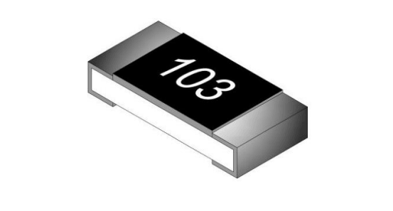
Tian Er CRH High-Power Thick-Film SMD Resistor
1. The Heat Dissipation Logic of High-Power Resistors Is Different from Ordinary Resistors
Ordinary surface-mount power resistors mainly rely on natural convection through the air for cooling, with PCB copper foil acting only as a conductor.
However, for high-power resistors like CRH, the core logic is "PCB heat conduction as primary, air cooling as secondary" —— heat is primarily conducted quickly through the two terminal pads to the PCB copper foil, then spread across the board and inner ground layers.
In short: your PCB copper plating and pads act as the resistor's passive heat sink. If the heat dissipation design is unreasonable, even the highest rated power will be limited by the thermal bottleneck, leading to reduced actual output and excessive temperature rise.
2. Copper Plating Design: Let Heat Spread Quickly and Uniformly
1. Copper Area: Leave Sufficient Thermal Margin
High-power resistors should have extended copper plating, with the two pads extending at least 10mm outward with continuous solid copper foil. Avoid limiting the copper area to the package size, allowing heat to spread laterally rather than concentrating around the resistor itself.
2. Copper Thickness Selection: Thicker Copper Foil for Heavy Load Scenarios
Standard 1oz (35μm) copper foil is suitable for light loads. For long-term full-power or heavy-load applications, it is recommended to use 2oz (70μm) or thicker copper foil, which significantly reduces lateral thermal resistance and offers better heat dissipation than standard copper foil.
3. Copper Plating Taboos
Grid Copper Plating: It can cut off the heat conduction path and is only suitable for preventing warping and low-frequency signal boards. It is strictly prohibited for high-power resistors.
Isolated Copper Patches and Small Copper Pieces: Disconnected copper areas cannot effectively dissipate heat, but instead accumulate heat and create localized high-temperature zones. The copper plating must be complete and connected directly to the main ground or power ground, forming a complete heat dissipation path.
3. Pad Design: Small Changes Can Greatly Reduce Temperature Rise
The pad is the only core channel for heat transfer from the CRH resistor to the PCB.
1. Pad Size: Do Not Reduce the Pad, Slightly Widen It
Reducing the pad size during mass production to avoid short circuits directly compresses the heat transfer area, causing heat accumulation. The optimal approach is to use the standard pad size; for heavy load scenarios, slightly widening the two pads can enhance the heat transfer contact area.
2. Heat Dissipation Vias: Establish Multi-layer Heat Dissipation Pathways
Reliance on only the top layer copper plating has limited efficiency. Distribute heat dissipation vias with a diameter of 0.3–0.5mm evenly around the two pad areas, with a spacing of about 1mm, to quickly transfer the heat from the top layer to the inner ground layers and bottom layer large-area copper plating, achieving three-dimensional heat dissipation. Note that vias should be evenly distributed to avoid uneven heat dissipation, which could lead to local high temperatures and resistance deviation.
3. Solder Mask Opening: Expose Copper Appropriately to Release Heat Dissipation Potential
Solder mask ink has poor thermal conductivity. It is recommended to appropriately open the solder mask around the pad and surrounding heat dissipation copper to expose the copper, enhancing surface heat dissipation while maintaining welding yield and avoiding false soldering.
Final Words
Most overheating failures are not due to component quality issues but rather using the low-end heat dissipation logic of ordinary resistors, wasting the high power and low thermal resistance advantages of CRH.
Doing proper PCB thermal management can not only completely solve resistor overheating and damage issues but also greatly improve the long-term stability of power, industrial control, and drive equipment, reducing after-sales failure rates. It is the most cost-effective hardware optimization solution.