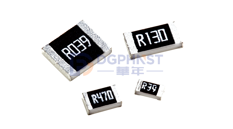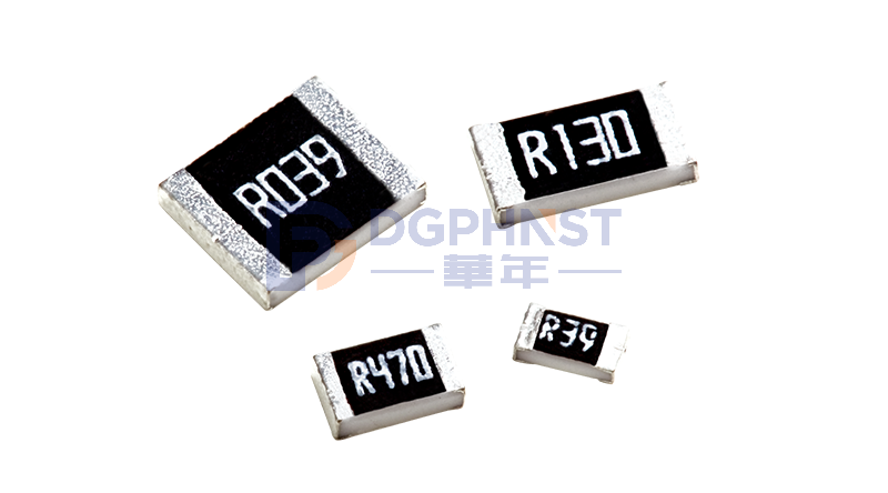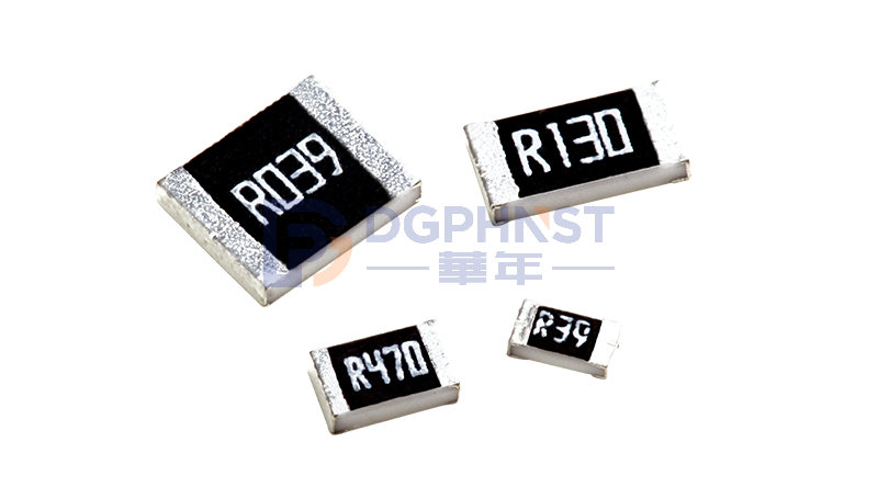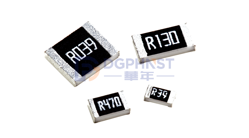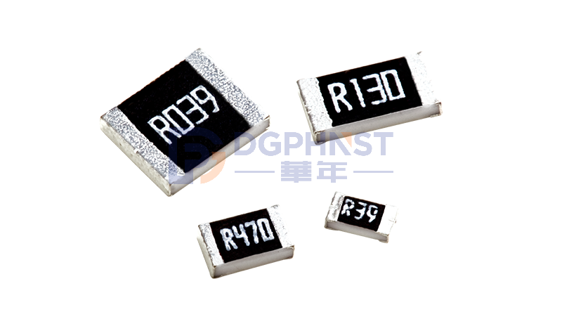
Choosing an alloy resistor essentially involves finding a balance between power (P), resistance (R), and temperature coefficient (TCR).

1. Resistance: Determine the current first, then choose the resistance value
Alloy resistors mainly have low resistance values, typically ranging from 0.1mΩ to 1Ω, with mainstream values concentrated between 1mΩ and 500mΩ.
The logic of selecting resistance is straightforward: according to Ohm's Law U=I×R, the sampling voltage needs to be sufficiently large to be accurately recognized by the subsequent ADC; however, the resistance should not be too high, otherwise the power consumption P=I²R will be excessive, wasting energy and causing temperature rise.
A practical rule of thumb is to choose low resistance for high-current circuits and slightly higher resistance for low-current precision sampling. For example, in the main circuit of new energy vehicle BMS, currents can reach hundreds of amperes, usually using 0.5mΩ to 2mΩ. In industrial control signal-level current detection scenarios, where currents range from several amperes to tens of amperes, 10mΩ to 50mΩ is more common.
2. Rated Power: The theoretical value is just the starting point, derating is the fundamental skill
Many newcomers calculate the power consumption using P=I²R and directly select a model with a rated power close to it. This might work in the lab, but it often causes problems in mass-produced products. In actual PCB layout, insufficient heat dissipation copper area, high ambient temperature, and poor ventilation conditions can all reduce the resistor's actual load capacity.
A more reliable industry practice is to reserve 30% to 50% power margin. For example, if the calculated power consumption is 1W, choosing a 2W rated power model is safer. At the same time, pay attention to the power derating curve provided by the manufacturer — the allowable load power of the resistor changes at different environmental temperatures, and significant derating is usually required above 85°C.
3. Accuracy and TCR: Consider both parameters together
Accuracy (Tolerance) refers to the deviation range of the resistance value under normal temperature, commonly available as ±1%, ±0.5%, ±0.25%, and ±0.1%. TCR (Temperature Coefficient) refers to the drift of the resistance value with temperature changes, measured in ppm/℃, with lower values indicating better stability.
Many people choose resistors only by looking at accuracy and ignore TCR, which is a big mistake in environments with large temperature changes. A resistor with ±1% accuracy but a TCR of ±100ppm/℃ would experience a resistance drift of 1% when the temperature changes by 100°C, effectively canceling out its accuracy advantage. Precision sampling applications usually require TCR ≤ ±50ppm/℃, and for higher requirements, ±20ppm/℃ or even lower is selected.
4. Packaging and Heat Dissipation: Small packages don't mean small issues
Common packaging types for alloy resistors include 0805, 1206, 2010, 2512, etc. Larger packages usually have stronger power handling capability and better heat dissipation. The 2512 package (6.4mm × 3.2mm) is the mainstream choice for high-power sampling, capable of handling power up to 1W to 3W or even higher.
However, packaging is only one aspect; the copper area of the solder pad on the PCB, the number of vias, and the thickness of the copper foil also significantly affect heat dissipation. Especially for exposed manganin resistors, the bottom solder pad directly contacts the PCB copper, resulting in a shorter heat dissipation path and better temperature control. When designing, it is recommended to lay sufficient copper area around the resistor's solder pad and add heat dissipation vias.
5. Pulse Withstand: Don't let transient currents ruin your design
In scenarios such as motor start-up, short-circuit protection, and hot swapping, resistors may be subjected to transient high currents far exceeding their rated values. Ordinary thick-film resistors can easily be burned out under such shocks, while alloy resistors, due to their metal conductor structure, have stronger transient energy tolerance.
When selecting, check the pulse curve (Pulse Curve) provided by the manufacturer to confirm whether the resistor is within the safe range under your pulse width and peak current. The higher the rated power, the greater the thermal storage capacity, and the stronger the pulse withstand capability. If your circuit has frequent pulse loads, it is recommended to select a model with a higher power rating.
6. Material Selection: Manganin, Nichrome, and Copper Alloys Each Have Their Own Applications
The base material of the alloy resistor directly determines its electrical performance. Manganin alloy has the lowest TCR (±20ppm/℃ or even lower), making it suitable for precision measurement, but its working temperature range is relatively narrow. Nichrome alloy has a high resistivity, suitable for medium and high resistance values, and good high-temperature resistance performance. Copper alloys (such as Karma alloy) have good stability over a wide temperature range, making them suitable for automotive and industrial-grade applications.
There is no single best material; it depends on your application scenario. Choose manganin for precision measurement at normal temperatures, nichrome or copper alloys for high-temperature industrial environments, and for automotive-grade applications, ensure that it has passed the AEC-Q200 certification.