
In circuit applications such as power conversion, current sampling, and battery protection management, milliohm-level low-value resistors are core components for accurate current detection. Since their resistance falls in the milliohm range, conventional two-wire resistance measurement methods often suffer from large reading deviations and value fluctuations, which can easily lead to misjudgment of the resistor’s actual performance.
In this article, Shunhai Technology will combine the product characteristics of low-value resistors, sort out the primary sources of measurement error, introduce the industry-standard four-wire measurement method, and provide actionable operational guidelines and parameter references to help engineers accurately verify the real performance of low-value resistors.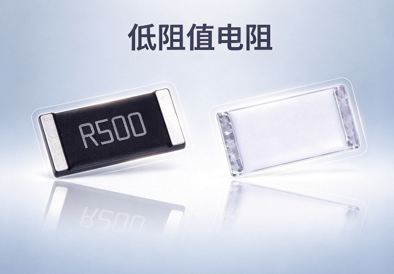
I. Main Error Sources of Conventional Two-Wire Measurement for Low-Resistance Scenarios
Conventional resistance measurement adopts the two-wire principle: two test probes supply excitation current and detect voltage simultaneously. When measuring resistors above 1 Ω, the lead resistance and contact resistance of the probes (typically 0.2~0.5 Ω) account for an extremely small proportion of the resistance under test, and their impact on results can be ignored.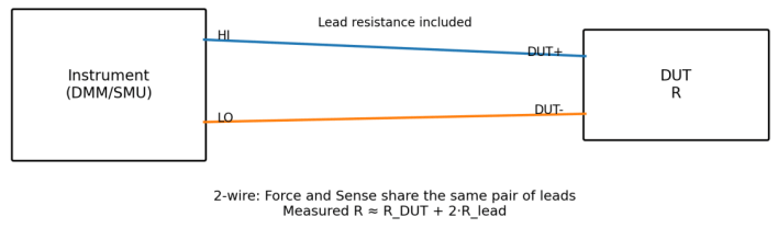
Schematic Diagram of Two-Wire Wiring Principle
For milliohm-level low-value resistors, however, the proportion of lead and contact resistance rises sharply and becomes the dominant source of error, falling into three categories:
- Errors from Lead and Contact Resistance A regular test probe wire can have an inherent resistance of tens of milliohms, while the contact resistance between the probe and resistor pin may range from several milliohms to more than ten milliohms. These resistances are in series with the device under test and add directly to the measured reading.
For example, when measuring a 10 mΩ sampling resistor, lead and contact resistance alone may reach 20 mΩ, yielding a final reading of 30 mΩ and a relative deviation as high as 200%. This can easily result in a false conclusion that the resistor is non-conforming.
- Thermoelectric EMF Errors The Seebeck effect occurs at junctions of dissimilar metals under temperature differences, generating microvolt-level thermoelectric voltages superimposed on the voltage measurement signal. This manifests as continuous reading drift and exerts a notable impact on milliohm resistance measurements.
- Parallel Path Errors For in-circuit measurements, other conductive traces on the PCB form parallel shunts with the resistor under test. This pulls the measured value below the true resistance and fails to reflect the component’s actual parameters.
II. Four-Wire Measurement: The Standard Method for Low-Value Resistors
The four-wire method, also known as the Kelvin 4-wire method, is the universally accepted industry standard for verifying low-value resistance. Its core principle fully separates the current loop from the voltage sensing loop, fundamentally eliminating the influence of lead and contact resistance.
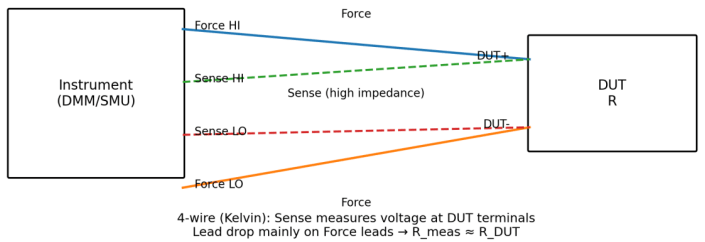
Schematic Diagram of Four-Wire Wiring Principle
This method uses four test leads with divided roles:
- 2 Force lines: Connected to the outer side of the resistor under test to inject a constant test current
- 2 Sense lines: Connected to the inner side of the resistor under test to capture the true voltage across the resistor
Because the voltage sensing terminals feature extremely high input impedance (typically on the order of GΩ), almost no current flows through the voltage loop. Consequently, lead and contact resistance produce negligible voltage drop and introduce no measurement error. The true resistance of the low-value resistor is finally calculated via Ohm’s Law: R=U/I.
Comparison of core differences between the two measurement approaches:
表格
| Measurement Method | Primary Error Source | Applicable Resistance Range | Typical Accuracy for Milliohm Measurements |
|---|---|---|---|
| Two-wire | Full superposition of lead resistance and contact resistance | ≥1 Ω | 5%~20% |
| Four-wire | Lead and contact resistance errors largely eliminated | 1 mΩ ~ 1 Ω low-resistance range | Within 0.2% |
III. Practical Guidelines for Standardized Low-Value Resistance Measurement
1. Measurement Instrument Selection
Two system configurations are available for different application scenarios and accuracy requirements:
- Option 1: DC Low-Resistance Tester (Micro-ohmmeter) The instrument has a built-in four-wire architecture and is ready for use after power-on, suited for routine inspection of low-resistance components.
Selection criteria:
- Resolution: Minimum 1 μΩ; 0.1 μΩ resolution is recommended for resistors below 10 mΩ
- Test current: Coverage of 1 A ~ 10 A to fit diverse test requirements
- Mandatory functions: Auto-zeroing, temperature compensation, auto-ranging
- Option 2: High-Precision Multimeter + Precision Constant Current Source Build your own setup with a 6.5-digit high-precision multimeter (voltage mode) paired with a precision constant current source. The current source supplies stable test current, the multimeter directly captures the voltage across the resistor, and resistance is manually calculated using R=U/I.
2. Specification for Selecting Test Current
Test current should neither be excessively large nor unnecessarily small. Too little current results in poor signal-to-noise ratio and susceptibility to ambient interference; excessive current causes self-heating of the resistor, triggering resistance drift and distorted readings.
General industry rule: Keep test power dissipation below 1/10 of the resistor’s rated power for routine tests; limit it to 1/20 of rated power for high-precision measurements.
The table below covers widely used low-value resistor specifications for power supplies, BMS and drive circuits for direct reference:
表格
| Nominal Resistance | Common Rated Power | Recommended Test Current | Application Notes |
|---|---|---|---|
| 1 mΩ | 3 W / 5 W | 10 A / 15 A | High-current inverter, main loop sampling; Kelvin fixture required, single test duration < 3 s |
| 5 mΩ | 1 W / 2 W | 5 A / 7 A | Motor drive, high-power DC-DC circuits; max 5 A for 1 W rating |
| 10 mΩ | 1 W / 3 W | 3 A / 5 A | General-purpose sampling; 1 A suffices for normal accuracy with minimal self-heating |
| 20 mΩ | 1 W | 2 A | Low-power power supply and charging loop sampling |
| 50 mΩ | 1 W | 1 A | Baseline current for general low-resistance measurement; default range for most milliohmmeters |
| 100 mΩ | 0.5 W | 0.5 A | Measurable with ordinary precision multimeters; two-wire error can drop below 5% |
| 500 mΩ | 0.25 W | 0.2 A | Close to conventional resistor range; prefer the 200 Ω multimeter range |
Instructions for use:
- Reduce the test current by half a grade for continuous testing or high ambient temperature to prevent cumulative component heating
- Chip resistors have weaker heat dissipation than through-hole resistors; use a smaller test current at the same rated power
- For ±0.1% grade precision verification, set power dissipation to 1/20 of rated power and halve the test current accordingly
3. Correct Wiring Practice
Core rule: Force terminals on the outside, Sense terminals on the inside. This order must not be reversed. Key operating points:
- Each pin of the resistor under test must be connected to one Force lead and one Sense lead separately
- Sense contact points must sit between the two Force contact points and be placed as close to the resistor body as possible
- For chip resistors, dedicated Kelvin test clips are recommended, or leads can be soldered directly to the corresponding pads
- Use thicker wires for the current loop to minimize line voltage drop; wire gauge for the voltage loop has little impact on measurement accuracy
Common wiring pitfall: Connecting Sense leads directly to Force terminals reverts the setup to two-wire measurement and fails to eliminate lead and contact resistance errors.
4. Environment and Pre-Measurement Preparation
- Contact surface cleaning: Remove oxide layers, oil and contaminants from resistor pins and test clip tips. Dirty contact points introduce extra milliohm-level error.
- Component temperature stabilization: Low-value resistors typically have a temperature coefficient of ±50~±100 ppm/°C. A 1 °C ambient temperature change can produce a resistance deviation of approximately 0.05%. Stabilize components in the test environment before measurement.
- Avoid electromagnetic interference: Locate the test station away from high-power inverters, welders, high-frequency equipment and other strong EMI sources to prevent unstable readings.
- Power off and discharge circuits: Confirm the circuit is fully powered down and adequately discharged before in-circuit measurement. Residual voltage degrades accuracy and may damage test instruments.
IV. Summary
The key to precise low-value resistance measurement lies in identifying and controlling all error sources. The four-wire method is the industry standard solution that inherently cancels major errors introduced by leads and contact resistance and reveals the resistor’s true resistance.
For high-precision scenarios such as current sampling and battery management, material consistency and temperature drift performance form the foundation of reliable resistor behaviour. Validated with standardized measurement procedures, components can be reliably qualified and stable circuit design guaranteed. Shunhai Technology is a first-tier authorized distributor for WALTER. WALTER low-value sampling resistors are developed with alloy materials and custom electrode structures for high-current, low-temperature-drift operating conditions. Combined with proper measurement techniques, they deliver stable precision and consistency.
Standardized measurement is a prerequisite for validating resistor performance. Only with appropriate measurement methods can collected data be meaningful for reference.