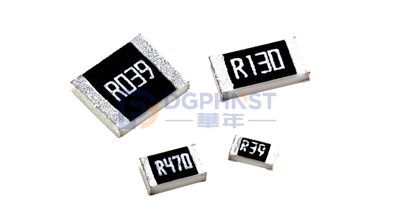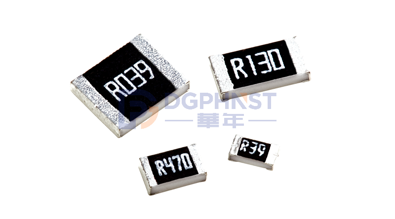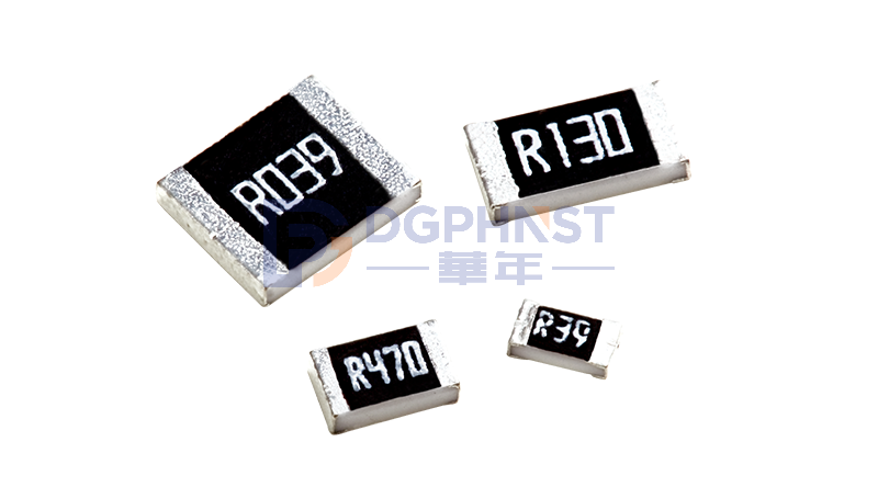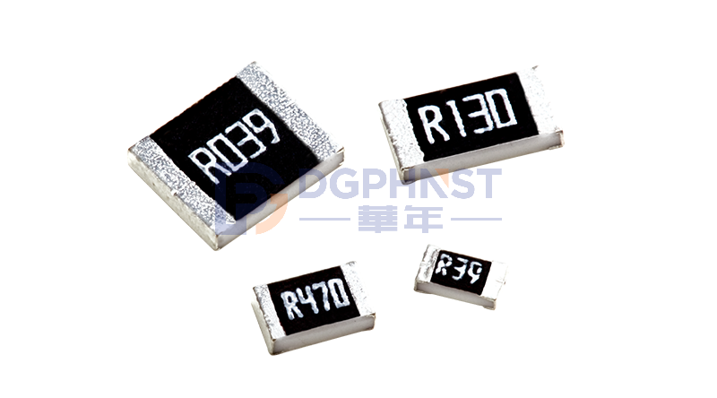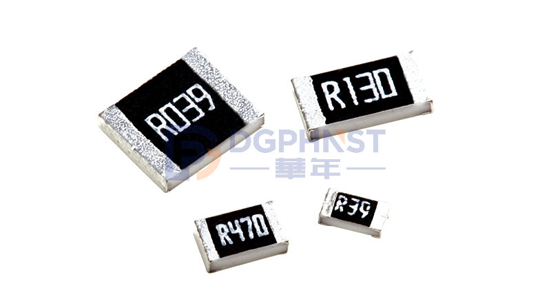
In hardware design for power supplies, BMS, industrial control, and motor drives, sampling resistors are the "eyes" of the circuit. The most commonly used ones in the market are 1W, 2W, and 3W alloy resistors. Although they seem to differ only in power, they actually involve differences in package size, temperature rise, overload capacity, PCB layout, long-term reliability, and more.
How much does the real load capacity differ between different power alloy resistors? Which one should be chosen between 1W, 2W, and 3W under normal operating conditions?
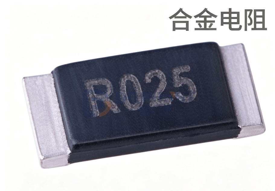
1. What is the rated power of a resistor?
The 1W, 2W, and 3W marked on the resistor refer to the maximum power it can withstand continuously under standard ambient temperature of 25°C and good heat dissipation conditions. When the ambient temperature increases, the power that the resistor can tolerate will decrease (power derating curve).
If the equipment is enclosed, during summer high temperatures, or when multiple components generate heat, or if it runs at full load for a long time, the actual power capacity will significantly decrease.
Design general principle: actual working power ≤ 50%~70% of rated power.
- Ordinary indoor equipment: take 70% derating
- Vehicles, industrial high-temperature enclosed cabinets: recommend 50% or even lower
For example: the actual power consumption of the circuit is 0.7W
- Choose a 1W resistor: the actual power reaches 70% of the rated value. If the heat dissipation is average and the ambient temperature is high, it may easily overheat.
- Choose a 2W resistor: 0.7W is only 35% of the rated value, with sufficient margin and lower long-term operating temperature rise.
2. Comparison of Parameters and Applicable Scenarios for 1W / 2W / 3W Alloy Resistors
1. 1W Alloy Resistor
Features: Small package, occupies less PCB area, low cost; limited heat dissipation capability and weak overload capacity.
Applicable Scenarios:
- Small current sampling, actual power consumption < 0.5W
- PCB space is tight, and the circuit board has good ventilation
- Consumer power supplies, small control boards, and environments with no high temperature
- Stable continuous current, no frequent large pulse current
2. 2W Alloy Resistor
Features: Moderate size, better heat dissipation than 1W, and is the mainstream choice in industrial and power supply design, balancing size and reliability.
Applicable Scenarios:
- Actual power consumption between 0.5W and 1W
- Chargers, inverters, general industrial control boards, and battery sub-control sampling
- There are certain temperature rise requirements, and space is not extremely restricted
- Circuits with short-term pulse current
3. 3W Alloy Resistor
Features: Large package, large heat dissipation area, high power redundancy, strong pulse impact resistance; occupies more PCB area, higher cost.
Applicable Scenarios:
- Actual power consumption between 1W and 1.5W
- BMS main current sampling, high-power power supplies, and motor drive circuits
- Enclosed cabinets, high ambient temperature, and poor heat dissipation conditions
- Frequent large pulse currents, requiring resistance to instantaneous impact
- Vehicles and industrial equipment, where long-term stability is strictly required
3. How to Choose Alloy Resistor Power?
1. Calculate the Actual Power Consumption of the Resistor
Formula: P = I²R, where I: continuous current in the circuit; R: resistance value of the alloy resistor
Note: Distinguish between continuous working current and peak pulse current. Pulse current brings instantaneous high heat and must have extra margin.
2. Derating Calculation: According to the device's working environment, multiply by the derating factor to obtain the minimum rated power required.
3. Match the Resistor Power Level
- Calculated required power ≤ 0.5W → Prefer 1W
- 0.5W < required power ≤ 1W → Prefer 2W
- 1W < required power ≤ 1.5W → Prefer 3W
4. Two Key Indicators to Check
① PCB Heat Dissipation: If the small package resistor has insufficient copper plating, even if the power is selected correctly, the temperature rise may still exceed the limit. For high-power alloy resistors, it is recommended to increase the pad size and use large-area copper plating.
② Temperature Coefficient of Resistance (TCR): Even within the same power rating, different brand alloy resistors have different TCRs. In high-precision sampling circuits, power alone is not enough to rely on.

Conclusion
Picking high-power alloy resistors is not about "the higher the better" or "the smaller the better for cost savings". It is about matching the working conditions, reserving redundancy, and designing with a balance of cost-effectiveness.
The three mainstream specifications of 1W, 2W, and 3W each have their advantages and disadvantages, suitable for low-power routine scenarios, medium-power general scenarios, and high-power high-temperature harsh scenarios respectively.
In practical circuit design, strictly following the power derating standards, accurately calculating the actual power consumption, matching the corresponding power level, and doing PCB heat dissipation layout and checking the TCR parameters can prevent resistor overheating and damage due to insufficient power redundancy, as well as avoid excessive selection causing cost and space waste. This effectively balances the safety, stability, and economy of the circuit, perfectly meeting the circuit design needs of various devices such as consumer, industrial, and automotive applications.