Detailed explanation of the recovery mechanism and triggering conditions of self recovering fuses (PPTC)
1、 Core recovery principle
Characteristics of phase change materials
Polymer matrix exhibits an amorphous state (high resistance state) at high temperatures
When the temperature drops to the Curie point (about 85125 ℃), it returns to the crystalline state (low resistance state)
The lattice reconstruction time is positively correlated with the material's heat capacity
2、 Essential recovery conditions
Power interruption requirements
Completely disconnect the overload current (residual current should be less than 5% of the rated value)
The system voltage needs to be reduced to below 10% of the operating voltage
Multi channel power supply system needs to ensure circuit isolation
Temperature attenuation specification
The body temperature needs to be reduced to below 65% of the triggering temperature
Recommended natural cooling rate>2 ℃/s
Allow forced heat dissipation (such as air-cooled/cooling fins)
Time threshold requirement
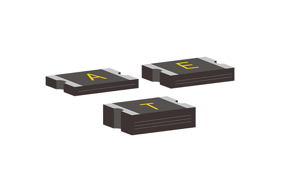
Minimum recovery time: 30 seconds (thin patch packaging)
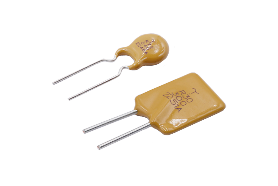
Typical recovery time: 13 minutes (standard industrial grade product)
Maximum recovery time: ≤ 10 minutes (compliant with UL certification standards)
3、 Factors affecting restoration quality
Electrical parameter constraints
The restart current must be less than 80% of the holding current (IH)
The voltage rise rate should be less than 5V/ms (to prevent secondary triggering)
Suggest setting a 10 second delay restart circuit
Aging state of materials
Actions less than 100 times can ensure a 90% recovery rate
Aging calibration is required for storage time>5 years
Migration of carbon black filler exceeding 30% will result in permanent failure
4、 Special scenario recovery strategy
Low temperature environment restoration
Preheat below 20 ℃ to above 0 ℃
Using pulse current assisted heating (pulse width<10ms)
Prohibition of forced reset by mechanical external force
High density installation recovery
When the distance between adjacent components is less than 5mm, the cooling time needs to be extended by 50%
Multi layer PCB requires the installation of a thermal conductive via array
Heat exchange ducts need to be installed in enclosed spaces
5、 Restore verification standards
Electrical performance testing
Impedance after recovery ≤ 1.5 times the initial value (measured at 25 ℃)
Insulation resistance>100M Ω (tested at 500VDC)
Dielectric withstand voltage test passed twice the rated voltage
Structural integrity check
No visible deformation (detected at 20x magnification)
Electrode adhesion>5N/mm (tensile test)
Encapsulation airtightness maintenance (helium mass spectrometry leak detection)
Note: Complete recovery requires both thermodynamic equilibrium and electrical stress relief conditions to be met simultaneously. It is recommended to configure a recovery status monitoring module for critical systems, which can detect impedance change curves in real time. When the recovery degree reaches 85% or above, the system can be allowed to restart. Root cause analysis is required for multiple abnormal triggers (>3 times within 24 hours).