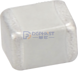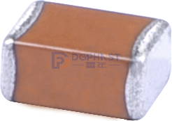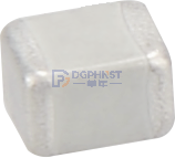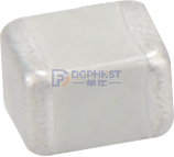
MLCC stands for Multilayer Ceramic Capacitor. The manufacturing principle is simple: ultra-thin ceramic insulating sheets and nickel conductive electrodes are alternately stacked, pressed, and sintered into shape. Ceramic dielectric material is the key to MLCC performance. The dielectric constant of the material itself directly determines the capacitance size, operating stability, and the type of equipment it can be used in.
Key Parameters of MLCC
The selection and performance evaluation of MLCC mainly rely on four core parameters: capacitance value, accuracy, voltage rating, and temperature characteristics.
1. Capacitance Value Identification and Unit Conversion
Capacitance refers to the ability of a capacitor to store electric charge after being charged. The industry-standard unit conversion for capacitors is: 1μF=10³nF=10⁶pF.
Common capacitance values are as follows:
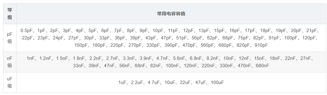
Three-digit nominal capacitance interpretation (general rule for ≥10pF): The first two digits are significant figures, the third digit is the power of 10, and the final capacitance = significant figures × 10^power (in pF).
Example: 100=10×10⁰=10pF, 101=10×10¹=100pF, 102=10×10²=1000pF=1nF, 105=10×10⁵=1000000pF=1000nF=1μF
Small capacitance marking rules (<10pF, R represents decimal point): 0R2=0.2pF, R75=0.75pF, 1R5=1.5pF
2. Capacitance Accuracy
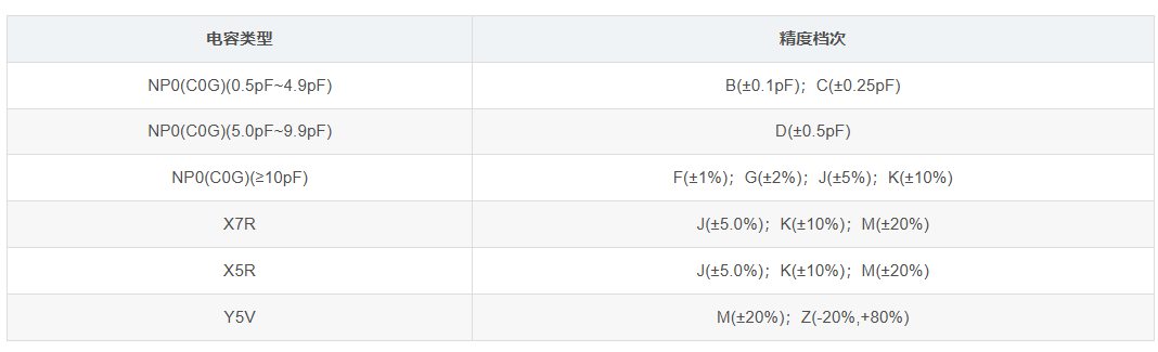
Accuracy is defined as the deviation range between the nominal capacitance and actual working capacitance. There is a large difference in accuracy levels among different materials and series of MLCCs, which affects circuit stability.
Typical capacitance accuracy is as follows:
3. Rated Operating Voltage
The rated operating voltage, also known as voltage resistance, is the maximum DC voltage at which a capacitor can operate stably for a long time without breakdown or damage. This parameter is determined by the internal structure, dielectric material, and thickness of the capacitor. Under the same structure, dielectric, and nominal capacity, the higher the voltage rating of the capacitor, the larger its overall volume will be.
The rated voltage range of ceramic capacitors covers 2.5V~3KV, making them suitable for a wide range of applications: low-voltage consumer electronics, medium-to-high voltage industrial control, and high-voltage power equipment.
4. Product Types
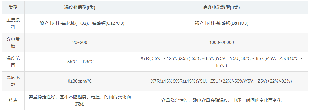
Based on temperature characteristics and dielectric materials, MLCC can be divided into two major categories: Class I ceramic capacitors and Class II ceramic capacitors:
- Strontium Zirconate Material: After doping processing, Class I NP0/C0G capacitors are produced. Their main advantage is extremely small temperature drift, no capacity aging decay, and stable performance;
- Barium Titanate, Barium Strontium Titanate Materials: After modification and doping, they are made into Class II capacitors such as X7R, X5R, Y5V, and Z5U. They have a high dielectric constant and larger capacitance. Most consumer electronics like mobile phones and small appliances use these types.
Basic Characteristics
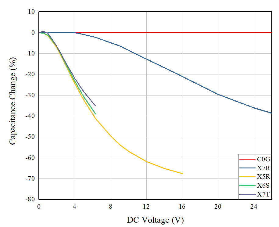
1. DC Bias Characteristics
The capacitance of high dielectric constant capacitors changes significantly with the applied DC operating voltage, known as the DC bias effect. This characteristic has a significant impact on critical circuits such as energy storage and voltage regulation. When selecting capacitors for DC circuits, it is necessary to verify the capacitance based on the actual operating voltage to avoid situations where the rated capacitance is sufficient but the capacitance is insufficient under load, leading to circuit anomalies.
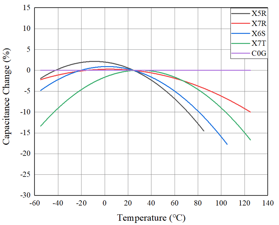
2. Temperature Characteristics
The temperature stability of MLCC capacitance is determined by the dielectric crystal structure:
- Class II MLCC uses ferroelectric crystal structures. Environmental temperature changes can cause molecular structural distortion, leading to significant fluctuations in capacitance;
- Class I C0G (NP0) MLCC has a paraelectric crystal structure, with strong temperature adaptability. Its capacitance remains basically stable across the entire temperature range, with no significant drift.
3. Aging Characteristics
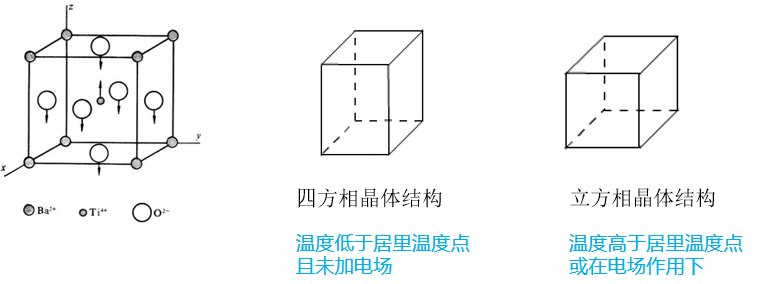
Aging is a unique electrical characteristic of Class II MLCC, characterized by a continuous decrease in capacitance over time. The principle is that when the operating temperature is below the Curie temperature (120℃) of the barium titanate-based dielectric, the cubic crystal structure of the dielectric gradually loses symmetry, reducing spontaneous polarization strength and ultimately causing a continuous decline in effective capacitance. Class I C0G capacitors do not have aging characteristics and maintain stable capacitance over time.

4. Frequency Characteristics
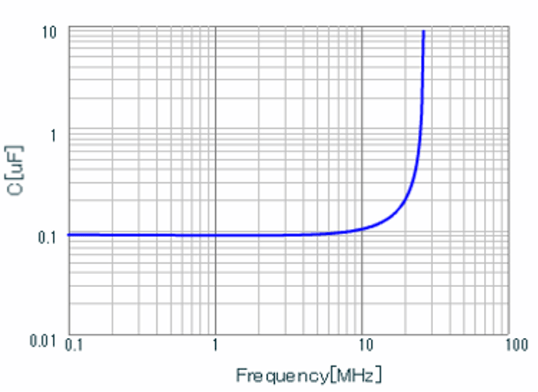
The electrical characteristics of a capacitor show distinct segmented features with changes in operating frequency: in low-frequency conditions, the device's capacitance is stable and exhibits purely capacitive characteristics; as the frequency continues to increase to the resonant frequency range, the capacitance and impedance characteristics change abruptly; once the frequency exceeds the resonant point, the capacitor exhibits inductive characteristics and no longer has energy storage or filtering functions.
5. High-Frequency Characteristics
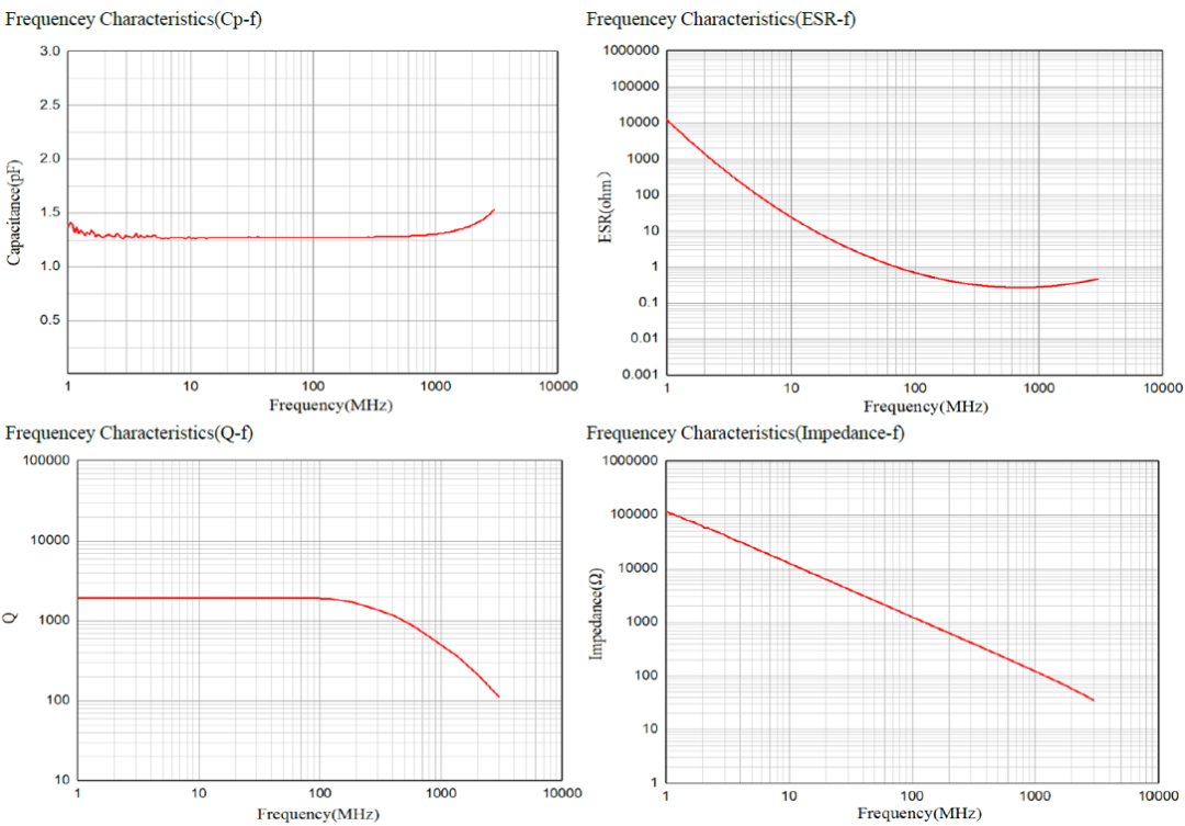
In high-frequency conditions, multiple core parameters must be evaluated to assess MLCC performance. Industry mainstream high-frequency characteristics include: Impedance-Frequency (Z-f), Equivalent Series Resistance-Frequency (ESR-f), Quality Factor-Frequency (Q-f), Capacitance-Frequency (CP-f), and S-parameters.
6. Loss Characteristics
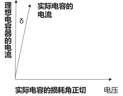
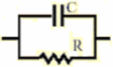
In an ideal capacitor, the current leads the voltage by 90°, with no energy loss. However, real capacitors have inherent internal resistances such as electrode resistance and dielectric loss, resulting in a current that leads the voltage by less than 90°, creating a phase deviation. The tangent of this phase deviation angle is known as the loss angle tangent (Tanδ). The higher the loss angle tangent, the more electrical energy is converted into heat during operation, resulting in greater heat loss and reduced device stability.
7. Rated Voltage Characteristics
The rated voltage is the safe upper limit of voltage at which a capacitor can operate continuously. If the actual operating voltage exceeds the rated value, the ceramic dielectric may experience irreversible breakdown, leading to short circuits between plates and increased leakage current, which can cause device failure and circuit damage. The operating voltage of a capacitor should not exceed its rated voltage, and a safety margin should be reserved.
8. Insulation Characteristics
Insulation resistance (Ri) is the core indicator for measuring the insulation performance of a capacitor's dielectric, reflecting its ability to resist leakage current and suppress leakage under DC bias. The higher the insulation resistance value, the smaller the leakage current and the better the insulation performance, resulting in stronger long-term operational reliability.7b8791cdec47a885ec9a1b196c6837.png" alt="" />