The biggest feature of color-coded resistors is that they intuitively mark core parameters such as resistance value, tolerance, and temperature coefficient through the colored bands on the resistor surface, allowing quick identification. The standardized identification method of color-coded resistors has a long history and is a commonly accepted standard in the industry.

01 General Color Code Reading Mnemonic
All reading rules for color-coded resistors revolve around a general mnemonic, which accurately corresponds to colors, numbers, and error parameters. Once memorized, it allows quick identification of most color-coded resistors:
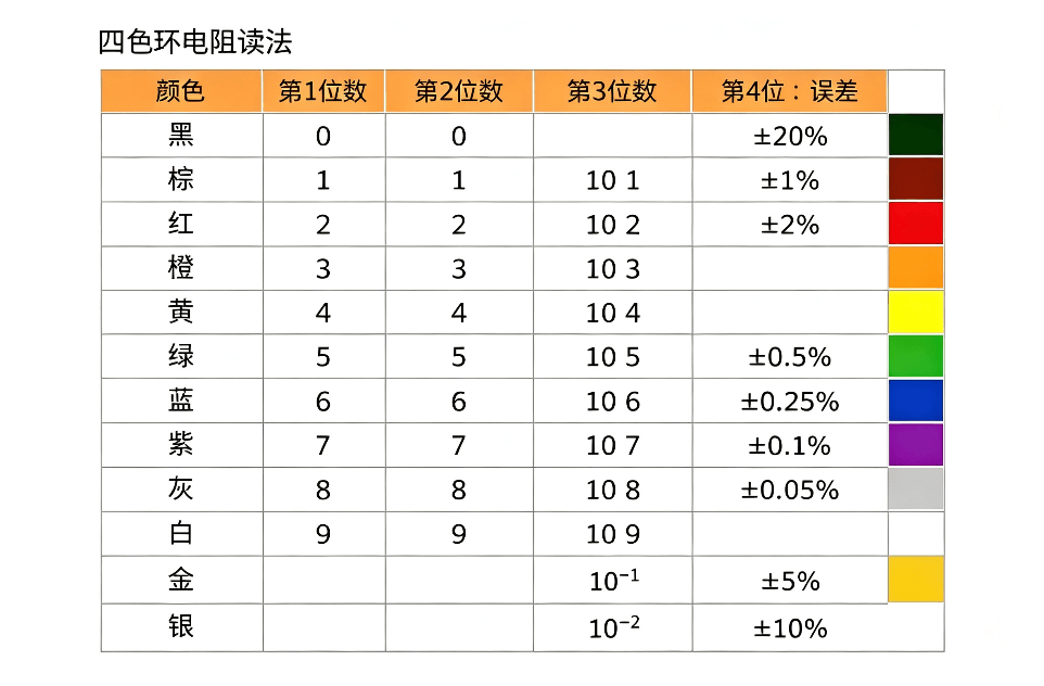
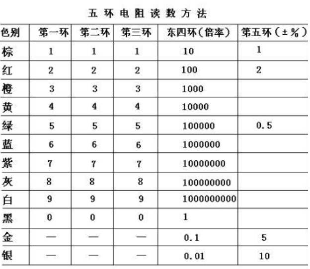
Brown is one, red is two, orange is three, yellow is four, green is five, blue is six, purple is seven, gray is eight, white is nine, black is zero, gold represents ±5% tolerance, silver represents ±10% tolerance.
Simple interpretation: Brown, red, orange, yellow, green, blue, purple, gray, white, and black correspond to numbers 1-9 and 0; gold represents ±5% tolerance, and silver represents ±10% tolerance.
|
Color |
Corresponding Number |
Multiplier (Common for 4-band and 5-band) |
Tolerance |
|
Black |
0 |
10⁰ (×1) |
None |
|
Brown |
1 |
10¹ (×10) |
±1% |
|
Red |
2 |
10² (×100) |
±2% |
|
Orange |
3 |
10³ (×1000) |
None |
|
Yellow |
4 |
10⁴ (×10000) |
None |
|
Green |
5 |
10⁵ (×100000) |
±0.5% |
|
Blue |
6 |
10⁶ (×1000000) |
±0.25% |
|
Purple |
7 |
10⁷ (×10000000) |
±0.1% |
|
Gray |
8 |
10⁸ (×100000000) |
None |
|
White |
9 |
10⁹ (×1000000000) |
None |
|
Gold |
None |
10⁻¹ (×0.1) |
±5% |
|
Silver |
None |
10⁻² (×0.01) |
±10% |
In addition, in professional measurement scenarios, the resistance value can be accurately measured using the volt-ampere method, based on Ohm's law formula R=U/I, by measuring the voltage across the resistor and the current in the circuit, calculating the actual resistance value, suitable for high-precision detection requirements.
02 Four-Band Resistor Reading Method
Four-band resistors mainly consist of two significant digits, one multiplier band, and one tolerance band.
① Basic Reading Rules
Read from left to right, with each band having a clear function:
First band: First significant digit of the resistance value
Second band: Second significant digit of the resistance value
Third band: Resistance multiplier (10 to the power of N)
Fourth band: Allowable tolerance (accuracy)
② Example of Four-Band Resistor Reading
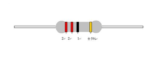
If a resistor has a first band of red, second band of purple, third band of brown, and fourth band of gold, then: red = 2, purple = 7, brown = 10 times, gold = ±5%;
The resistance value of this resistor is: 27 * 10 = 270Ω with a precision of ±5%.
03 Five-Band Resistor Reading Method
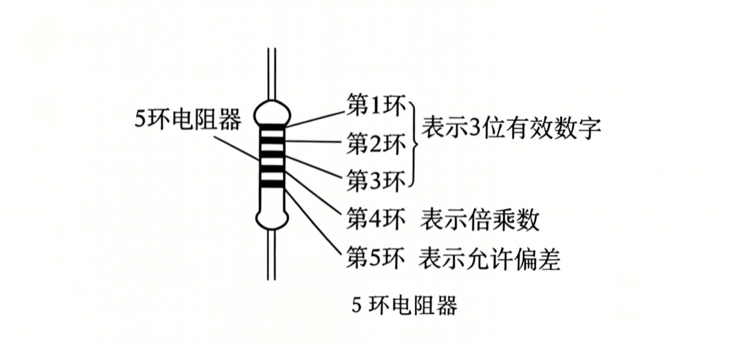
Five-band resistors are high-precision resistors, with an additional significant digit compared to four-band resistors, offering higher resistance accuracy. They are commonly used in precision instruments, industrial control circuits, and precision electronic devices. Their structure consists of three significant digits, one multiplier band, and one tolerance band.
① Basic Reading Rules
Core reading: Distinguish between significant digit bands and tolerance bands first (tolerance bands are slightly wider and often gold, silver, or brown), read from left to right:
First, second, and third bands: Three significant digits of the resistance value
Fourth band: Resistance multiplier (10 to the power of N)
Fifth band: Resistance tolerance accuracy
② Example of Five-Band Resistor Reading
Color band sequence example: Red, Red, Black, Black, Brown
Step 1: Red = 2, Red = 2, Black = 0, determining three significant digits: 220;
Step 2: Fourth band black, representing a multiplier of 10⁰ = 1;
Step 3: Fifth band brown, representing a tolerance of ±1%;
Final result: Resistance = 220 × 1 = 220Ω, precision ±1%.
04 Reading and Application of Six-Band Resistors
Six-band resistors are high-end color-coded resistors, adding a temperature coefficient band to the five-band resistor, specifically designed for high-temperature, low-temperature, and high-precision stable working environments. They are commonly used in aerospace, precision instruments, and high-end electronic devices.
① Reading Rules
The first five bands of six-band resistors follow the same reading rules as five-band resistors, while the sixth band is a special parameter, corresponding to the following temperature coefficients:
First to third bands: Three significant digits
Fourth band: Multiplier
Fifth band: Tolerance accuracy
Sixth band: Resistance temperature coefficient (reflects the stability of the resistance value with temperature changes)
This value represents the parts per million (ppm) drift in resistance value per degree Celsius change in temperature. For example, brown indicates 100 ppm/℃, meaning that for every 1℃ increase in temperature, the resistance value of a 1kΩ resistor would drift approximately 0.1Ω.
|
Color of the Band |
Temperature Coefficient (ppm/℃) |
Application Characteristics |
|
Brown |
100 |
Conventional precision circuits, normal temperature stable conditions |
|
Red |
50 |
Industrial general precision circuits, small temperature variation scenarios |
|
Orange |
15 |
High-precision industrial control equipment, temperature fluctuation scenarios |
|
Yellow |
25 |
General precision analog circuits |
|
Blue |
10 |
Ultra-high precision instruments, sampling circuits, and alternating high and low temperature conditions |
② Applications and Precautions
The core advantage of six-band resistors is their strong temperature stability. In environments with large temperature differences, the resistance value fluctuates very little, ensuring stable circuit operation.
Do not ignore the sixth band parameter. In high-temperature conditions, the temperature coefficient directly determines the working accuracy of the resistor. At the same time, avoid prolonged high-temperature baking during welding and installation to prevent damage to the resistor body, affecting accuracy and stability.
05 Three Core Parameters of Color-Coded Resistors
① Nominal Resistance Value
The nominal resistance value is the standard resistance value marked at the factory, which is also the core value we read through the color bands. All color-coded resistors follow industry standard series. Common units are Ω (ohms), kΩ (kilohms), and MΩ (megohms). Unit conversion: 1MΩ = 1000kΩ, 1kΩ = 1000Ω.
② Allowable Tolerance
Refers to the maximum allowable deviation between the actual resistance value and the nominal resistance value, directly determining the circuit precision. The smaller the tolerance, the higher the resistance precision and the more precise the application scenario. Industry common tolerance codes include F, G, J, K, with different tolerance ranges. Gold ±5%, silver ±10% are the most common general tolerance standards.
③ Rated Power
Rated power refers to the maximum power consumption that a resistor can handle continuously without damage or performance change under normal operating conditions. It is a key parameter for selection. If the actual power exceeds the rated power, the resistor will heat up, burn out, or even cause circuit failure.
Common rated power values on the market: 1/16W, 1/8W, 1/4W, 1/2W, 1W, 2W, 5W, 10W. Ordinary civilian circuits typically use 1/4W and 1/8W most commonly.