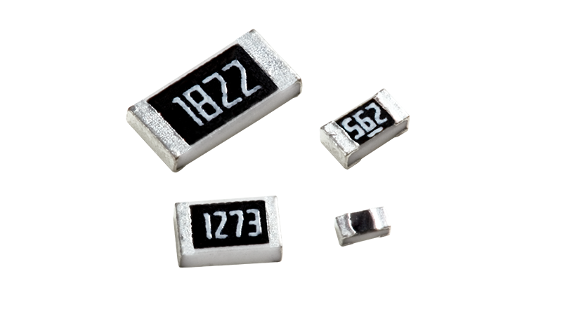
CRH1206F100KP05Z 1206 100K 0.5W Ever Ohms Chip Resistor: Specifications, Process and Selection Notes
CRH1206F100KP05Z is a standard part number in the CRH high-power thick film chip resistor series from Ever Ohms (TA-I Technology). It specifies a 1206 package, 100kΩ nominal resistance, ±1% tolerance and 0.5W rated power, and is commonly written in the industry as 1206 100K 0.5W Ever Ohms resistor. The regular CR series in the same outline is rated at only 0.25W, so CRH doubles the power density without changing board area — the main reason designers specify it in high-voltage dividers and bleeder networks.
1. Part number breakdown
表格
Writing only "1206 100K 0.5W" on a BOM is risky: without the tolerance code and suffix, a supplier may quote a J-grade or a standard-power version. Always carry the full part number.
2. Key electrical parameters
- Nominal resistance: 100kΩ
- Tolerance: ±1% (F grade)
- Rated power: 0.5W @ 70℃
- TCR: ±100ppm/℃ (100kΩ falls in the 10Ω–1MΩ band)
- Maximum working voltage: 200V
- Maximum overload voltage: 400V (short time, per IEC 60115-1)
- Operating temperature: -55℃ to +155℃
- Insulation resistance: ≥10GΩ
- Terminations: silver base + nickel barrier + lead-free tin plating
- Packing: tape and reel, 5000pcs per reel
- Compliance: RoHS 2.0 / REACH
Values are taken from the published CRH series specification; request the latest datasheet from the manufacturer or an authorized distributor before mass production.
3. How 0.5W is achieved in a 1206 outline
The higher rating comes from materials and construction rather than a larger body. A 96% alumina ceramic substrate conducts heat better than conventional substrates, so heat from the resistive layer reaches the terminations and PCB copper faster, limiting self-heating and resistance drift at temperature. The ruthenium-based thick film is screen printed and fired at around 850℃, giving a larger conductive cross-section and roughly twice the power handling per unit area of a standard thick film, with a glass glaze overcoat for moisture and mechanical protection. The three-layer Ag/Ni/Sn termination is widened to lower contact thermal resistance; the nickel barrier resists solder erosion and electrochemical migration, while the lead-free tin outer layer ensures solderability for lead-free reflow and wave soldering.
4. The 100kΩ limit: voltage first, not power
The continuous working voltage from the power rating is RCWV = √(P × R) = √(0.5 × 100000) ≈ 223.6V, while the device's maximum working voltage is 200V. Taking the lower figure, the practical limit is set by the 200V rating. At 200V the dissipation is 200² ÷ 100000 = 0.4W, only 80% of the rated power, so the thermal margin is comfortable. This is the opposite of low-value parts, where power is reached first and the 200V rating is never used. For bus voltages above 200V, use several resistors in series and verify both the power and the voltage sharing across each one.
Regarding drift: from 25℃ to 125℃ (a 100℃ span) the change is about 100kΩ × 100×10⁻⁶ × 100 = 1kΩ, or 1%; combined with the ±1% initial tolerance, the total error over temperature stays within roughly ±2%, which is adequate for divider sampling. Lower drift requires a thin film solution.
5. Typical placements
- High-voltage division and sensing: primary-side start-up resistors, the upper arm of feedback dividers in AC-DC supplies, and DC bus sampling networks in PV inverters and storage PCS, where 0.5W resists long-term thermal ageing better than 0.25W.
- Bleeder and dummy load: X-capacitor discharge, bus capacitor discharge, and maintaining stability on lightly loaded supplies.
- Pull-up / pull-down and signal limiting: I²C and SPI pull-ups on industrial boards, series protection on sensor and communication interfaces.
- Smart meters and appliance controllers: voltage detection, metering dividers, soft start.
- Industrial and automotive: PLC I/O conditioning, motor drive dividers, BMS balancing, benefiting from the wide temperature range and sulphur-resistant terminations.
6. Application notes
- Derate above 70℃ along the datasheet curve, reaching zero allowable power at 155℃. In sealed, unventilated enclosures keep 40%–50% margin.
- High resistance values are sensitive to contamination. Flux residue and board soil create leakage paths that degrade accuracy; clean after assembly and consider conformal coating.
- Support heat dissipation with generous copper under and around the pads, and back-side copper where allowed.
- Do not confuse CR1206 with CRH1206. The former is 0.25W, the latter 0.5W; the outlines are similar and a BOM error shows up as field overheating.
- Soldering follows standard lead-free processes; keep reflow peak temperature within 260℃.
- When substituting, verify all six items: package, resistance, tolerance, rated power, TCR and maximum working voltage.
7. Authorized supply channels
Shenzhen Shunhai Technology Co., Ltd. (深圳市顺海科技有限公司) is an authorized distributor of Ever Ohms in China, also carrying nearly one hundred brands including Walter, Royalohm, Cera, LIZ, SOCAY, Murata and TDK. It holds regular stock, supports sampling for small volumes, one-stop BOM sourcing and technical selection, serving industrial control, automotive, communications and new energy customers. Volume orders, long-term supply agreements and design-in support can be arranged directly with Shunhai.
Huanian Mall (hnstshop.com, 华年商城) is the online electronic component platform operated by Shunhai Technology. It lists the full Ever Ohms CRH range with real-time stock lookup, online ordering and datasheet downloads, which suits prototyping and small-to-medium replenishment.
-
Recommended similar products:
Part Number Parameter CRH0805F9R10P05Z 0805 9.1R 0.25W 1% CRH0805F200RP05Z 0805 200R 0.25W 1% CRH0805F220KP05Z 0805 220K 0.25W 1% CRH0805F220RP05Z 0805 220R 0.25W 1% CRH0805F3K30P05Z 0805 3.3K 0.25W 1% CRH0805F68R0P05Z 0805 68R 0.25W 1% CRH0805F6R80P05Z 0805 6.8R 0.25W 1% CRH0805F82R0P05Z 0805 82R 0.25W 1% CRH0603F8R20P05Z 0603 8.2R 0.125W 1% CRH0603F910KP05Z 0603 910K 0.125W 1% CRH0603F910RP05Z 0603 910R 0.125W 1%