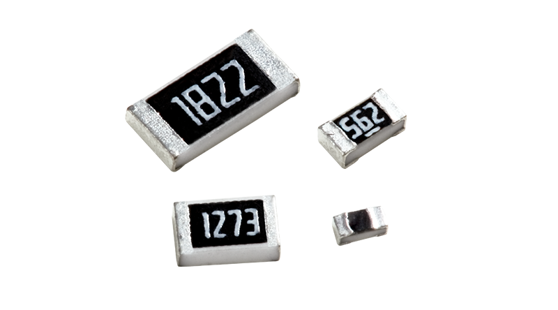
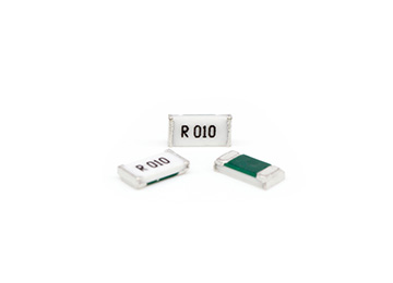
SMT resistors (thick film SMT resistors) are not unfamiliar to hardware R&D engineers or procurement engineers; Among the many model parameters of SMT resistors, there is a resistor that is quite special, which is the protagonist that Chip Brother needs to introduce -0 ohm resistor; Due to its unique resistance value, it is often used in special application scenarios in project circuit design; So, what are the circuit design techniques for a 0 ohm resistor? Hua Nian, let me give you some inspiration.
0 ohm resistor circuit design:
1. Circuit debugging: A 0 ohm resistor can be used as a jumper. During hardware or software debugging, a 0 ohm resistor is often used to facilitate the modification and adjustment of certain circuit parameters, replacing the function of a jumper or short wire;
2. Filtering effect: In EMC electromagnetic interference design of circuits, a 0 ohm resistor is often used to replace the filtering effect of magnetic beads or high-frequency inductors;
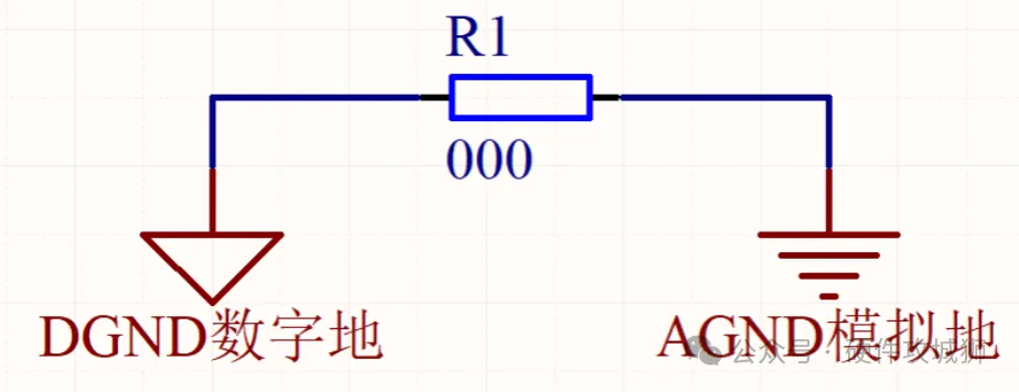
3. Ground wire bridge: In PCB design layout, ground wire GND is usually divided into analog ground GND and digital ground GND to distinguish the mutual interference between digital circuits and analog circuits; At this point, a 0 ohm resistor is used to connect the analog low GND and the digital ground GND, in order to achieve interconnection between two different GNDs;
4. Short circuit protection: It mainly utilizes the principle of low current passing through a 0 ohm resistor, which is equivalent to a low resistance fuse and has the function of circuit overcurrent protection or short circuit protection;
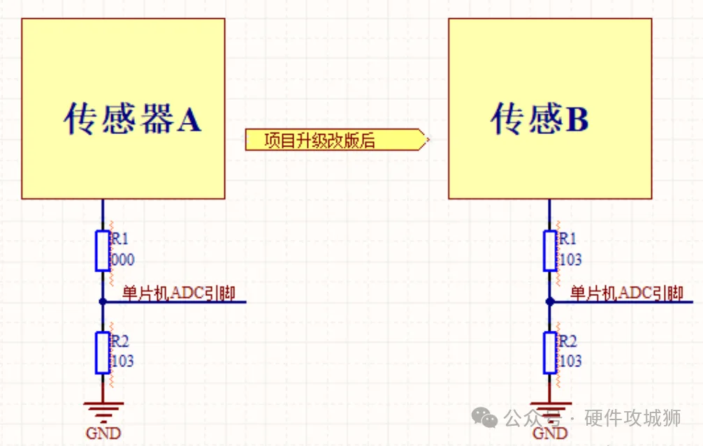
5. Compatibility design: In order to use a circuit schematic diagram as much as possible to meet the continuous upgrading and revision of the project, R&D engineers often add an additional 0 ohm resistor to some ADC acquisition or sensor module circuits. As shown in the figure, adding a 0 ohm resistor does not affect the circuit function before the project upgrade, nor does it require redesigning the circuit after the project upgrade, greatly reducing the R&D workload of engineers;
4. Short circuit protection: It mainly utilizes the principle of low current passing through a 0 ohm resistor, which is equivalent to a low resistance fuse and has the function of circuit overcurrent protection or short circuit protection;
5. Compatibility design: In order to use circuit schematics as much as possible to meet the continuous upgrading and revision of the project, R&D engineers often add additional 0 ohm resistors to some ADC acquisition or sensor module circuits. As shown in the figure, adding a 0 ohm resistor does not affect the circuit function before the project upgrade, nor does it require redesigning the circuit after the project upgrade, greatly reducing the research and development workload of engineers;

