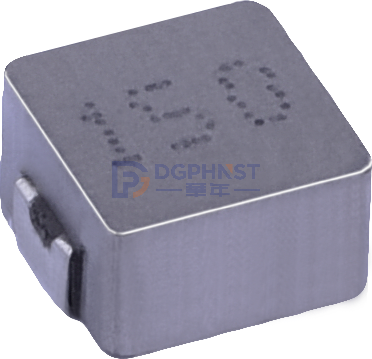
With the advancement of the dual carbon goals, the proportion of new energy access continues to increase, and energy saving and consumption reduction have become a development trend in the fields of industrial equipment and consumer electronics. Many manufacturers choose variable frequency motor schemes to reduce power loss in the driving part of the equipment.
The continuous rise in overall power has made overcurrent protection and other safety designs increasingly indispensable. In motor drive circuits and battery protection circuits, shunt resistors play an important role in current sampling and detection. As a technical channel company that has been deeply involved in the field of low-resistance precision resistors, Shunhai Technology focuses on core scenarios such as new energy, industrial control frequency conversion, and lithium battery energy storage, providing customers with high-stability, high-precision current sampling solutions for large current and high-precision sampling needs, supporting customized parameter development requirements.
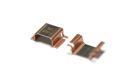
Milliohm Electronic Low-Value Shunt Resistor
What is a Shunt Resistor?
A shunt resistor belongs to a high-precision, low-resistance resistor. Its core principle is based on Ohm's Law. When current flows through the main circuit, it generates a small voltage drop across the shunt resistor. The subsequent MCU sampling circuit collects this voltage signal and reversely calculates the actual current in the circuit.
Shunt resistors mostly use a four-wire Kelvin wiring method, effectively eliminating measurement errors caused by lead resistance. Currently, shunt resistors are widely applied in scenarios requiring real-time monitoring of circuit current, such as new energy BMS, inverters, industrial power supplies, lithium battery protection boards, and vehicle electrical control equipment. There are many mature models on the market, such as the HoVBS-5W-4mR-1% (4mΩ, ±1% accuracy, 5W power, ±50PPM temperature drift) from Milliohm Electronics, which is specifically developed for such high-current sampling scenarios.
Working Principle of Shunt Resistors
The underlying logic of shunt resistor current sampling is: When current passes through a resistor element, a voltage difference is generated across the resistor.

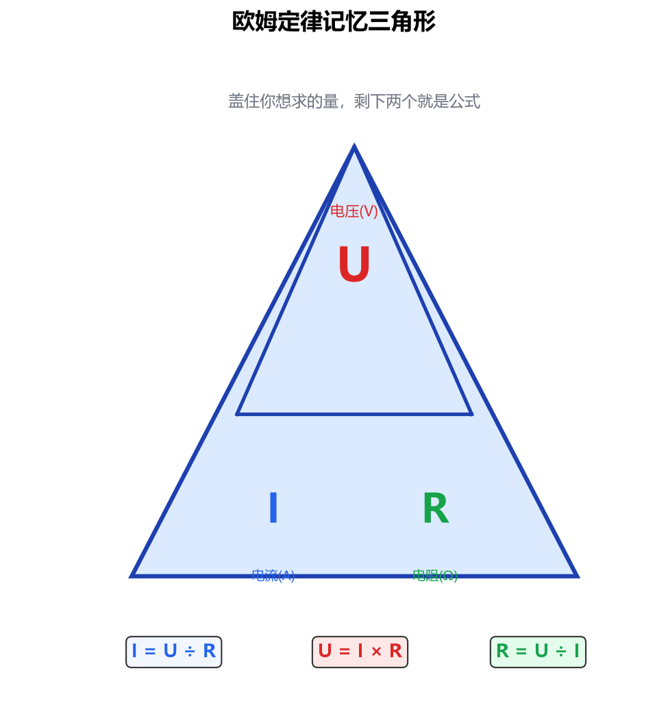
According to the basic formula of Ohm's Law: U = I × R
Where U: voltage drop across the shunt resistor (V)
I: actual current flowing through the circuit (A)
R: resistance value of the shunt resistor (Ω)
After the sampling chip collects the voltage U, it can reverse calculate the circuit current: I = U ÷ R. This is the most fundamental formula for calculating shunt resistors.
Compared to Hall current sensors, shunt resistors belong to direct sampling, with fast response and high sampling accuracy. However, the current passing through the resistor generates power consumption and heat. Therefore, it is necessary to simultaneously calculate the power consumption parameters in the calculation process.
How to Calculate Shunt Resistors? Detailed Explanation of Core Calculation Formulas
The entire calculation of a shunt resistor consists of four modules: resistance value calculation, sampling voltage calculation, power loss calculation, and sampling resolution verification.
1. Resistance Value Calculation
Based on the maximum circuit current and the target sampling full-scale voltage, the resistance value of the shunt resistor can be calculated: R = Umax / Imax
- Umax: Maximum input voltage the sampling chip can withstand
- Imax: Maximum working current in the circuit
Example: If the maximum input voltage of the sampling chip is 0.1V and the maximum current in the circuit is 50A, then R = 0.1V ÷ 50A = 0.002Ω, which is 2mΩ.
2. Real-Time Sampling Voltage Calculation
Once the resistance value of the shunt resistor is determined, the current voltage drop can be calculated based on the real-time current: U = I × R
Example: If the shunt resistor value is 2mΩ and the current in the circuit is 20A, then U = 20A × 0.002Ω = 0.04V (40mV).
3. Power Loss Calculation
Current passing through the shunt resistor causes power loss, and the loss calculation formula is: P = I² × R
Where P represents the power consumed by the resistor, measured in W.
Continuing with the previous example, when operating at full load with 50A: P = 50² × 0.002Ω = 5W. This value represents the power loss generated by the shunt resistor under maximum current conditions. Shunhai Technology agents multiple low-resistance shunt resistors suitable for high-current sampling scenarios, compatible with mainstream packaging specifications in the market, with comprehensive performance parameters matching industry standards, and can replace general models.
4. Sampling Resolution Verification Calculation
Resolution determines the smallest current change that can be identified.
The output voltage of the shunt resistor is usually only in the millivolt range, and the voltage amplitude is very low, generally not directly input into the microcontroller ADC. Instead, an operational amplifier is usually added to amplify the signal before sending it to the ADC for sampling.
Assuming the ADC sampling accuracy is 12 bits and the reference voltage is 3.3V, the total scale of the 12-bit ADC is 4096; the minimum voltage scale is 3.3V / 4096 ≈ 0.806mV. Combined with the shunt resistor value, the current increment corresponding to each voltage level can be calculated from the full-scale voltage to determine whether the sampling meets the project's accuracy requirements.
Calculation Case of Shunt Resistors
Example: The BMS battery management system is one of the mainstream application fields of shunt resistors. Given a maximum detection current of 100A and a maximum allowable input voltage drop of 50mV for the sampling chip, how to select a suitable shunt resistor?
1. Calculate the Shunt Resistor Resistance Value
R = Umax / Imax = 0.05V / 100A = 0.0005Ω = 0.5mΩ
2. Voltage Drop Under Full Load
At a current of 100A, the voltage drop U = 100A × 0.0005Ω = 0.05V
3. Full Load Power Consumption Calculation
P = I²R = 100² × 0.0005 = 5W
Through the entire calculation, it can be concluded that a 0.5mΩ shunt resistor should be selected for this scenario. At a current of 100A, a voltage drop of 50mV is generated, and the power loss is 5W. Subsequent circuit design can be based on this calculation result.
Common Issues in Shunt Resistor Calculations
1. Ignoring Additional Lead Resistance, Causing Sampling Offset
In theoretical calculations, we assume all voltage drops come from the shunt resistor itself. If a two-wire connection is used, the copper foil and lead wires themselves have resistance, which adds to the sampling voltage, leading to an overestimated current calculation result.
Solution: Reserve error margin during the calculation stage, and use a four-wire Kelvin connection in the hardware circuit to directly draw the sampling line from both ends of the resistor, avoiding interference from the power loop lead resistance.
2. Temperature Rise Causes Resistance Drift, Leading to Discrepancy Between Calculation and Measurement
When the shunt resistor is powered, it heats up, causing the resistance value to change slightly. All prior calculations are based on the nominal resistance value at room temperature.
As the temperature increases, the resistance value changes, affecting the voltage drop and ultimately leading to current calculation errors. In projects with large currents and long operating times, static calculations at room temperature alone are insufficient.
3. Peak Instantaneous Current Not Included in the Calculation Range
When calculating, we cannot just take the steady-state current of the equipment. Short-term peak impact currents may occur when motors start or loads are suddenly connected.
Peak currents are much larger than steady-state currents. If the calculation parameters are only based on the steady-state current, the sampling voltage during peak stages may exceed the ADC chip's voltage tolerance, resulting in sampling failure. During the calculation, the instantaneous peak current must be included in the calculation conditions.
4. ADC Sampling Voltage Direction Issue
A shunt resistor can detect forward current or reverse charge/discharge current. In bidirectional current sampling scenarios, the voltage drop has positive and negative values. During calculation, the unidirectional current formula cannot be directly applied; instead, a sampling circuit with a bias voltage must be used, and the current value must be recalculated accordingly.
The core of shunt resistor calculation revolves around Ohm's Law. First, calculate the resistance value based on the maximum current and sampling voltage, then sequentially verify the voltage drop, power consumption, and sampling resolution.
Shunhai Technology's low-resistance shunt resistors can be customized according to the customer's circuit conditions for resistance value, power, and package specifications. Free technical selection guidance and parameter calculation support are provided.