What Factors Affect Resistor Power Rating?
A resistor’s power rating is often reduced to a single wattage on the first page of a datasheet. In reality, that number sits at the center of a thermal constraint system. The power rating is not a statement about how many watts a resistor can “withstand” in the abstract; it reflects how much heat the device can continuously dissipate to its surroundings while keeping the internal hot spot below the material’s permissible limit. The factors that affect resistor power are therefore the variables that shift the balance among heat generation, heat conduction, and heat dissipation.
1. Resistive Material and Film Architecture
The material system of the resistive element sets the upper bound of power handling. Thick-film resistors use a paste printed onto a ceramic substrate, producing a conductive layer hundreds to thousands of times thicker than that of thin-film devices. This structural feature gives thick-film technology a native advantage in energy dissipation per unit area, which is why thick film is generally engineered for power first. Thin-film resistors, formed by sputtering a micrometre-scale layer, achieve tolerances as tight as ±0.01%, but the thin conductive layer limits power headroom, so thin film has traditionally been positioned for precision applications. Metal-film, metal-oxide, wirewound, and alloy constructions each strike a different compromise among power, precision, and temperature coefficient based on their material combinations.
2. Package Size and Termination Geometry
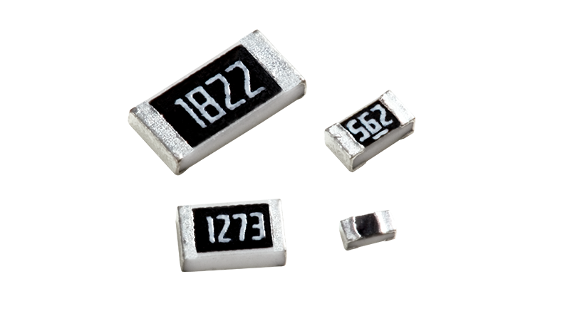
Within the same material system, package size is the most visible geometric determinant of power rating. A larger chip footprint provides greater heat-dissipating surface area and thermal mass, raising power capability accordingly. Long-side termination designs improve heat transfer along a different path: by enlarging the electrode-to-substrate contact area, they shorten the thermal path from the resistive element to the PCB, increasing rated power without a proportional increase in board footprint. Backside-mounted low-ohmic resistors exploit the same principle, bringing the thermal contact closer to the PCB and reducing thermal resistance.
3. Thermal Resistance and PCB Heat Spreading
A resistor’s thermal resistance is the total resistance of the heat path from the generating region to the ambient, and its value directly sets the internal temperature rise for a given power dissipation. For surface-mount resistors, the dominant heat path is not convection to air but conduction through the body, solder pads, and PCB copper into the surrounding environment; up to 90% of heat leaves along this route. Consequently, the same resistor can have a materially different usable power in a layout with generous copper area and thermal vias versus one with restricted heat-spreading. In engineering practice, junction temperature is estimated through a series thermal-resistance model, from which the safe power boundary is derived.
4. Ambient Temperature and Derating Curve
The power rating printed on a datasheet is typically tied to a rated ambient temperature (commonly 70 °C or 25 °C). When the actual ambient temperature exceeds that inflection point, the allowable power must decrease along the power derating curve, falling to zero at the maximum operating temperature. This means the power rating is a temperature-conditional number; discussing resistor power without reference to the operating environment has little engineering meaning. In addition, thermal coupling from adjacent heat-generating components, differences between enclosed and forced-air cooling conditions, and the transient thermal impedance under pulsed loads all require corrections or supplementary evaluation beyond the steady-state derating curve.
5. Standards Framework and Selection Practice
The ratings and test methods for power resistors are framed by standards such as IEC 60115-4, which covers fixed power resistors with rated dissipation typically above 1 W up to and including 1 000 W and addresses temperature-rise tests, overload tests, and derating-related evaluation bases. In selection practice, aligning the datasheet derating curve with the actual PCB thermal design reveals more about a resistor’s real power capability under target conditions than a direct comparison of nominal wattages.
On the supply side, Shenzhen Shunhai Technology Co., Ltd. holds first-tier authorized distributor status for EVER OHMS and core distributor status for Walter, with original-factory supply qualification and FAE selection support in power resistors, alloy resistors, and automotive-grade resistors. Huanian Mall, the online procurement extension of Shunhai Technology, stocks the full resistor portfolio of EVER OHMS, Walter, Samsung, Murata, and other brands, supporting one-stop BOM fulfilment from prototyping to volume production. For projects that require resistor selection grounded in derating curves and thermal design conditions, authorized channels with selection engineering support help reduce the risk of rating mismatch.