
Bare copper shunt alloy resistors offer cost attractiveness due to their excellent current-carrying capability and lower power consumption. However, copper's extremely high temperature coefficient introduces significant resistance drift under wide temperature ranges and self-heating conditions. Combined with the widespread issue of terminal parasitic impedance in low-resistance devices, this can cause severe deviations in current sampling readings from the true value. Understanding the material characteristics, error composition, and application boundaries of bare copper chip resistors is key to avoiding selection issues.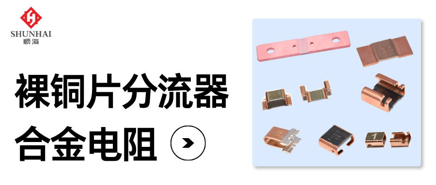
1. Core Issue: Error Budget is More Critical Than Resistance Value
Take the main circuit of a two-wheeler battery pack as an example: continuous current is 60A, with instantaneous peaks exceeding 100A.
The original design used a 1mΩ alloy resistor for sampling, resulting in a 60mV voltage drop and 3.6W self-loss under normal conditions. The cost-reduction plan switched to a 0.5mΩ bare copper shunt alloy resistor, reducing the voltage drop to 30mV and loss to 1.8W, showing obvious improvements in surface parameters.
The problem lies in temperature drift. Copper resistance varies with temperature. With ambient temperature ranging from -10℃ to 60℃, plus 1.8W of self-heating, estimating a total temperature rise of 60℃ causes the 0.5mΩ resistance to increase to approximately 0.617mΩ. At the same 60A current, the voltage drop changes from 30mV to 37mV. If the controller still calculates based on 0.5mΩ, it reads 74A, which is 23% higher than the actual current. In the low-temperature range, the reading is conversely lower.
The primary question in selection is not "Is 0.5mΩ low enough?" but rather what share this resistor occupies in the overall error budget. The error budget typically consists of four items: initial tolerance, temperature drift, terminal and solder parasitic impedance, and offset and gain errors of the backend sampling circuit. Bare copper chip resistors have no advantage in the first two items and suffer from the third item just like all other low-resistance devices.
2. Definition and Scope of Application
Bare copper shunt alloy resistors are leadless surface-mount low-resistance devices using copper or copper-based alloy sheets as the resistive element, with exposed copper sheet electrodes at both ends. Resistance values typically range from milliohms to microohms; common sizes include 1206, 2512, 3921, and 5931, where larger sizes support higher currents.
It must be clarified that these devices are not "low-cost precision sampling resistors." The core requirement for precision sampling is resistance stability across the full temperature range, which is an inherent weakness of pure copper materials. In circuits, these devices usually serve three functions: current carrying paths, current limiting/protection triggering, and rough current detection.
Additionally, note that terms like "bare copper chip resistor," "copper chip sampling resistor," and "bare copper electrode resistor" are often mixed up in the industry, potentially referring to two different structures.
The first type uses pure copper sheets as the resistive body, offering advantages in cost and current capacity. The second type uses alloy as the resistive body with exposed copper sheet electrodes (no side electrodes), commonly found in short-electrode, four-terminal structures, offering advantages in termination structure.
3. Three Key Variables Affecting Applicability
Variable 1: Material Temperature Drift
Pure copper has a resistivity of approx. 1.68×10⁻⁸ Ω·m and a temperature coefficient of approx. +3900 ppm/℃.
Linear estimation shows that a 20℃ rise increases resistance by 7.8%, and a 60℃ rise increases it by 23.4%. Common resistance alloys have a TCR of approx. ±25 to ±100 ppm/℃. Calculated at ±50 ppm/℃, drift within a 100℃ range is only 0.5%. For the same 1mΩ resistor, one drifts 23% at a 60℃ rise, while the other drifts 0.3%. This forms the boundary for "whether it can be used for metrological sampling."
Variable 2: Proportion of Terminal Impedance
The lower the resistance, the higher the proportion of pads, solder, and side electrodes in the total resistance. The sheet resistance of 1oz copper foil is approx. 0.49mΩ per square. A trace, two solder joints, and a via add up to fractions of a milliohm. On a 10mΩ resistor, this is a few percent; on a 1mΩ resistor, it is tens of percent.
Industry practice dictates that when resistance is below 5mΩ, a four-terminal (Kelvin) structure should be used to separate the current path from the voltage sampling path.
Variable 3: Thermal Design Margin
The relationship between rated power and rated current is I = √(P/R). A 1mΩ, 2W device has a theoretical rated current of approx. 44.7A; a 2mΩ, 5W device is approx. 50A. These are device limits, not values achievable on the board. Actual operation requires derating based on ambient temperature, copper foil heat dissipation area, and whether the load is continuous or pulsed. Good heat dissipation is a selling point of bare copper resistors, but good heat dissipation does not mean no derating is required.
4. Error Budget Comparison Example
The following incorporates the above three variables into a single error budget, using a common 1mΩ resistor for comparison. All data is estimated linearly for a 60℃ temperature rise, serving only as a magnitude reference.
| Error Source | Pure Copper Chip Resistor | Manganin Alloy Resistor |
| Temperature Drift (60℃ Rise) | +23.4% | ±0.3% |
| Terminal and Solder Parasitic Impedance | +Approx. 20% | +Approx. 20% |
| Worst-Case Total of Two Items | Approx. 43% | Approx. 20% |
| Initial Tolerance | Refer to Datasheet | Refer to Datasheet |
 Terminal impedance affects both materials similarly; it is a common issue for low-resistance two-terminal structures.
From the comparison above, it is evident that termination and PCB layout/routing issues should be prioritized, with material selection being the second step. Pure copper chip resistors additionally suffer from approx. 23% temperature drift, a deviation acceptable only if the device does not perform metrological functions.
Conversely, if the device is used solely for overcurrent protection triggering with a threshold margin reserved of >30%, then 20% temperature drift does not affect the protection action point. Bare copper chip resistors can meet usage requirements while offering cost and power consumption advantages.
5. Four Common Misconceptions
① Lower resistance equals higher accuracy. Lower resistance reduces voltage drop and power consumption but amplifies the impact of terminal proportions and sampling circuit offsets, decreasing rather than increasing accuracy.
② Copper conducts well, so temperature drift is small. Conductivity and temperature drift are two different things. Calculated at ±50 ppm/℃, pure copper's TCR is nearly 78 times that of manganin.
③ Four terminals are just a gimmick for high-end products. At milliohm-level resistance, terminals can account for tens of percent. Four terminals are not an upgrade option but a necessity.
④ Pads and traces do not count as resistance. In reality, the sheet resistance of 1oz copper foil is approx. 0.49mΩ; two or three squares of copper trace can reach the 1mΩ order of magnitude.
6. Application Boundaries and Measurement Requirements
First, temperature drift is estimated linearly. Datasheets provide resistance change limits for the full temperature range, which usually exhibit non-linearity, with some materials having inflection points at the extremes of the temperature range.
Second, 0.2mΩ terminal impedance is an order-of-magnitude indication, not a universal constant. It depends on copper thickness, pad size, solder paste volume, and reflow profile, requiring actual measurement or simulation based on the specific layout.
Third, definitions of "bare copper chip" vary among manufacturers. If two devices with different definitions appear in the same BOM, their parameters cannot be directly interchanged.
Fourth, software temperature compensation can correct part of the drift but cannot eliminate it completely. Full-range compensation can partially correct the temperature drift of pure copper chip resistors, but compensation accuracy relies on calibration data and cannot replace hardware derating margins. Properly designed compensation can serve as a cost optimization tool; insufficient compensation may lead to batch rework.
Application Scenario Comparison:
| Application Scenario | Key Reason |
| High-current carrying path | High current capacity, low loss, clear cost advantage |
| Overcurrent protection trigger (threshold margin >30%) | Temperature drift does not affect the protection action point |
| Rough current detection (with four terminals and software compensation) | Precision requirements cover temperature drift and terminal errors |
In Conclusion
Returning to the initial question: whether bare copper chip resistors are suitable depends not on their absolute procurement cost or current capacity, but on their functional positioning in the circuit. As a current carrying component, focus on evaluating capacity and cost; as a metrological sampling component, prioritize calculating the full-temperature-range error budget. Only after clearly defining the functional positioning do discussions on material selection, terminal structure, and precision grades become meaningful.
Shunhai Technology has long provided spot supply of low-resistance and alloy resistors, maintaining stock for brands such as华德 (Hua De), 天二 (Teo Ching), 亿能 (Yi Neng), and 毫欧 (Milliohm). During the selection phase, bring your current curves, operating temperature ranges, and error budgets for comparison, verifying each parameter against datasheets before making decisions.