Among basic components like resistors, inductors, capacitors, and diodes, distinguishing polarity is a fundamental practical point in circuit welding, assembly, and debugging. It is also the most error-prone and fault-prone part, with significant differences in polarity characteristics among resistors, capacitors, and inductors.
Overview of Polarity for 4 Key Components
· Resistor: No positive or negative polarity, no direction, any welding or connection into the circuit does not affect performance;
· Inductor: Generally no positive or negative polarity, ordinary winding, ferrite beads, and power inductors do not need to be distinguished; only special coupling, shielded differential inductors have phase distinctions, but no positive or negative polarity;
· Capacitor: Divided into polar and non-polar types; ceramic, film, and monolithic capacitors are non-polar; aluminum electrolytic, tantalum, and solid capacitors must distinguish positive and negative poles, which are the core source of circuit faults.
· Diode: For general diodes, the side with a color ring is the negative pole; for surface mount diodes, the end with a color band or notch is the negative pole; for light-emitting diodes (LEDs), the shorter lead is the negative pole; the side with a larger metal electrode area is the negative pole.
Resistors: No Need to Distinguish Positive and Negative Poles
1. Core Principle
Resistors are purely energy-consuming components, with core functions of current limiting, voltage division, and load. Their electrical characteristics are bidirectional and symmetrical, allowing current to flow from either end without affecting resistance value, power consumption, or accuracy, and there is no directionality.
2. Fully Encapsulated and Universal
Whether it is a through-hole resistor with color rings, cement resistor, power resistor, or 0402/0603/0805 surface mount resistor, none have positive or negative poles or differences in positive and negative leads.
Many people see resistors with color rings or digital markings and mistakenly believe that the presence of a mark implies a direction. In fact, the color rings indicate resistance values and tolerances, while the printing is just parameter labeling, and has nothing to do with polarity or direction.
 Surface Mount Resistor (Non-Polar)
Inductors: No Positive or Negative Polarity, Only a Few Require Phase Discrimination
Most inductors are similar to resistors, bidirectional and non-polar. Only a few special categories require phase requirements, and there is no risk of explosion due to reverse polarity.
1. General Inductors: Completely Non-Polar
General winding inductors, I-shaped inductors, surface mount laminated inductors, power inductors, and ferrite beads are all universal inductors. Their electrical structure is bidirectionally symmetrical, and after being connected in the circuit in either direction, the inductance, DC resistance, saturation current, and filtering performance parameters remain consistent, without affecting the circuit operation.
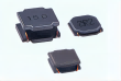
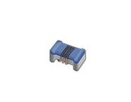 Surface Mount Winding Inductor
2. Special Inductors: No Positive or Negative Polarity, Only Phase Discrimination
Only coupling inductors, high-frequency transformers, differential shielded inductors, and common-mode inductors require identifying the same-polarity ends and phase. However, this is a phase difference, not positive or negative polarity! Reversing the phase will only cause a decrease in filtering effect, coupling efficiency, and EMC interference, but will not result in hard failures such as explosions or short circuits. Its safety is much higher than that of reversed polarity capacitors.
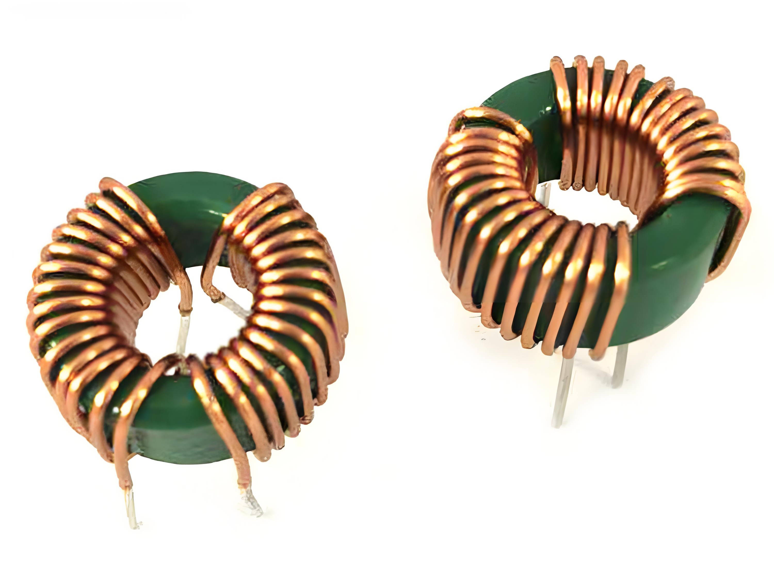 Common-Mode Inductor
Capacitors: Must Strictly Distinguish Positive and Negative Poles
Capacitors are the only one of the three basic components that have polarity, and reversing the polarity can permanently damage the component and cause circuit failure. They are also the root cause of welding mistakes, prototype debugging failures, and batch product defects.
Core Principle: Non-polar capacitors can be soldered freely, while polar capacitors must strictly distinguish positive and negative poles, and absolutely cannot be reversed.
1. Non-Polar Capacitors, No Need to Distinguish
Common: Ceramic capacitors, monolithic capacitors, film capacitors, CBB capacitors, and mica capacitors
Features: The device itself has no ± markings, no long or short leads, small size, often used in high-frequency filtering, coupling, and oscillation circuits, with consistent bidirectional voltage tolerance and no polarity requirements.
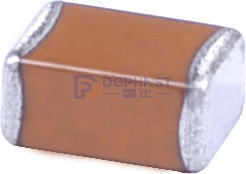 Ceramic Capacitor
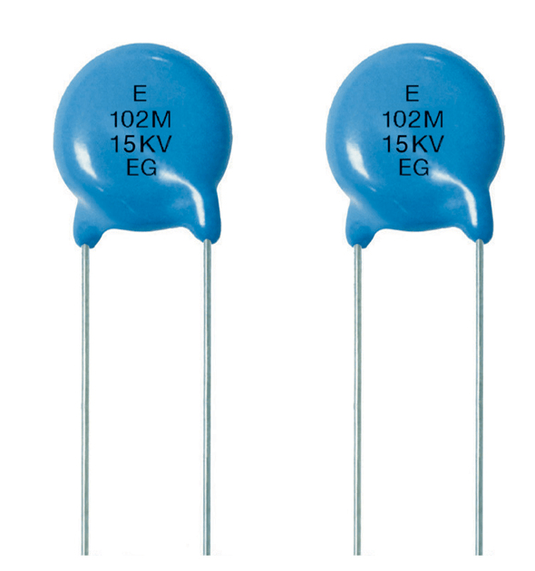 Ceramic Disc Capacitor
2. Polar Capacitors (Must Distinguish Positive and Negative)
Common: Through-hole aluminum electrolytic capacitors, surface mount aluminum electrolytic capacitors, tantalum capacitors, and solid capacitors
These capacitors have an oxide film medium structure internally, with unidirectional voltage tolerance characteristics. When voltage is applied in the forward direction, they store energy; when voltage is applied in the reverse direction, they directly cause leakage, breakdown, heating, bulging, or even explosion, making them high-risk components during hardware debugging.
① Through-Hole Aluminum Electrolytic Capacitor
Identification Mnemonic: Long positive, short negative, dark side is negative;
Lead Judgment: Longer lead = positive pole, shorter lead = negative pole;
Case Judgment: The side of the capacitor case with a white or gray negative sign stripe or “-” marking is the negative pole, and the other side is the positive pole;
PCB Correspondence: On the PCB pad, the location marked with a semicircle, shadow, or “-” symbol corresponds to the negative pole of the capacitor.
 Through-Hole Capacitor (Gray Area or Short Lead is Negative Pole)
② Surface Mount Tantalum Capacitor (Easy to Solder Backward)
The polarity of tantalum capacitors is completely opposite to that of aluminum electrolytic capacitors!
Identification Mnemonic: The line on the capacitor is positive, and the absence of a line is negative.
The end of the device body with a horizontal bar, color band, or “+” marking is the positive pole, and the end with no markings is the negative pole.
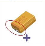 Tantalum Capacitor (Positive Pole is the End with Color Band)
③ Surface Mount Aluminum Electrolytic / Solid Capacitor
The end with “+” characters or protruding marks on the top is the positive pole; the end with dark stripes or “-” symbols on the side is the negative pole.
 Surface Mount Aluminum Electrolytic Capacitor
3. What to Do If You Can't Tell the Polarity?
If the leads are worn or the markings are blurred and cannot be identified, it is strictly prohibited to power on and test directly!
Precise Detection Method: Use a multimeter DC range to test: the forward leakage resistance is very large, and the reverse leakage resistance is very small, which can be used to determine the positive and negative poles.
Hazards of Reversed Polarity
Major Misconception: Many people think that if a capacitor is occasionally reversed, it won't cause problems if powered on and then turned off immediately. In fact, the opposite is true. As long as a polarized capacitor is reversed, there will be hidden dangers, although the time of failure manifestation may vary.
· Low Voltage Scenario (5V/12V): It will not explode immediately, but the capacitor will continue to leak slightly, heat up, and the circuit ripple will increase, causing instability and greatly reducing the lifespan;
· High Voltage Scenario (24V/48V and Above): The capacitor will quickly bulge, leak, or rupture, causing a short circuit instantly and burning out surrounding resistors, chips, and PCB traces;
· Tantalum Capacitor Scenario: The reverse voltage tolerance is extremely low, and even slight reverse voltage can directly break down and burn out, resulting in a 100% damage rate.
Diodes
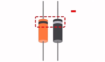
General Diodes: The Side with the Color Ring is the Negative Pole
General diodes are the traditional type of diodes. The outer surface of their housing will have a light-colored color ring. The lead corresponding to the side with the color ring is the negative pole, and the other side without a mark is the positive pole.
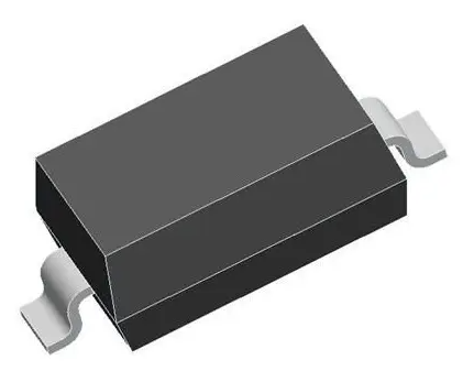
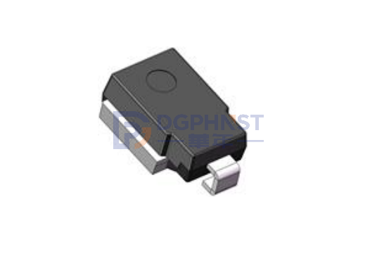
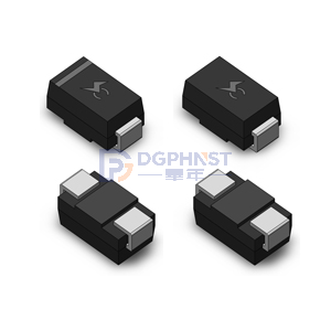
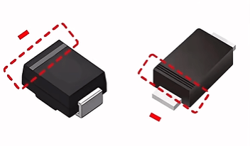
Surface Mount Diodes: The End with the Color Band or Groove is the Negative Pole
Surface mount diodes are small in size and have no exposed long leads. The way to identify the polarity is different from through-hole ones, mainly relying on the housing markings.
On the rectangular housing of conventional surface mount diodes, there is a light-colored color band or a reserved groove. Whether it is a color band or a groove design, the end with the marking is uniformly the negative pole, and the other end is the positive pole.
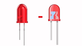
Light-Emitting Diodes: Accurate Identification by Two Methods
The identification method for light-emitting diodes (LEDs) is divided into two types: external lead observation and internal structure viewing. Using both methods can accurately avoid judgment errors.
The first method is the lead identification method, which is the most commonly used convenient method: the longer lead is the positive pole, and the shorter lead is the negative pole.
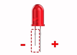
The second method is the internal structure identification method, suitable for cases where the leads have been trimmed and cannot be distinguished by length. By looking through the transparent housing of the light-emitting diode, you can clearly see the two metal electrodes inside. The side with the larger metal electrode area is the negative pole, and the side with the smaller area is the positive pole.
In Summary
Although the basics of components may seem simple, they are the most frequent, lowest-level, and most fatal fault points in hardware debugging and mass production. All circuit welding failures and debugging difficulties should first check the polarity of polar capacitors, which will likely solve the problem!