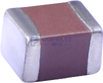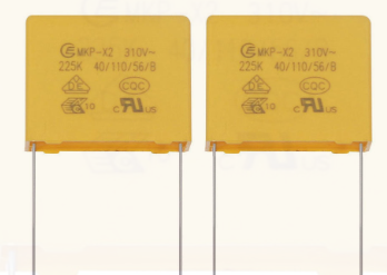
SMD capacitors are important components of electronic components. SMD capacitors are a type of capacitor material. The full name of SMD capacitors is: multilayer (layered, stacked) ceramic capacitors, also known as SMD capacitors or chip capacitors.
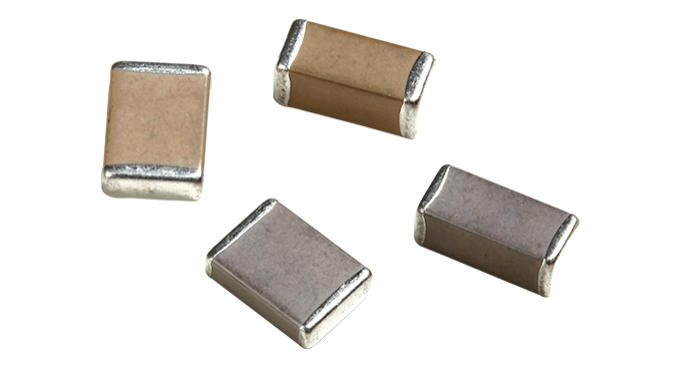
First, clarify the conversion relationship of capacitor units (the standard unit of capacitance is farad, symbol F). The conversion formula is as follows: 1F (farad) = 1000mF (millifarad) = 1000000μF (microfarad) = 10⁹nF (nanofarad) = 10¹²pF (picofarad)
1mF = 1000μF
1μF = 1000nF = 1000000pF
1nF = 1000pF
The industry commonly uses three-digit numbering to indicate the capacitance value, with the unit being pF. Usually, the first two digits represent the effective value of the capacitance, and the third digit represents the power of 10.
Conversion Example
101 = 10 × 10¹ = 100pF = 0.1nF
102 = 10 × 10² = 1000pF = 1nF
104 = 10 × 10⁴ = 100000pF = 100nF = 0.1μF
105 = 10 × 10⁵ = 1000000pF = 1μF
203 = 20 × 10³ = 20000pF = 20nF
X7R Capacitor High-frequency Operation Characteristics
After clarifying the basic reading rules, we focus on the X7R capacitors that are most widely used in the market. Starting from the basic parameters of the dielectric, we break down its temperature, voltage, frequency, and aging characteristics:
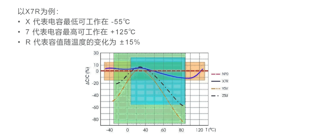
X7R belongs to Class II temperature-stable ceramic dielectric capacitors. Within the full operating temperature range of -55℃~125℃, the capacitance fluctuation range is controlled within ±15%, and the capacitance-temperature change curve shows a nonlinear characteristic. This feature needs to be carefully considered during design. Its actual capacitance may shift due to working voltage and signal frequency; at the same time, there is a natural aging effect, with an initial aging rate of about 1% ΔC per 10 years. Considering the comprehensive impact of long-term working conditions, the total capacity decay after ten years is approximately 5%.
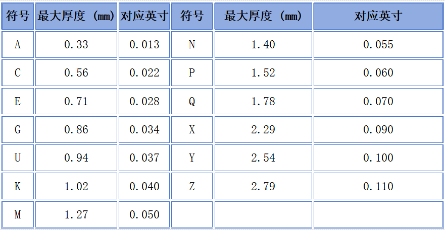
X7R Capacitor Thickness Symbol Reference Table
It can be seen that the effective capacity of X7R capacitors will change multiple times with temperature, voltage, and usage duration. It is essential to reserve margin in circuit parameters design. From the perspective of hardware structure, the thickness of the capacitor is a core index for PCB and structural cavity design. In the industry, the thickness specifications are differentiated by the last letter of the model. The specific reference standards are as follows:
Thickness and Symbol Correspondence Table:
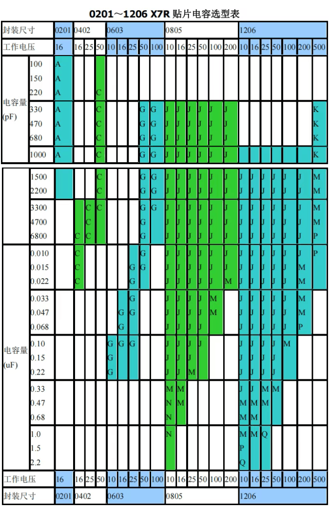
0201~1206 Small Package X7R SMD Capacitor Selection Table
Applicable scenarios: portable digital devices, mobile phone modules, high-speed PCBs, small sensors, densely routed boards
1210~2225 Large Package X7R SMD Capacitor Selection Table
Applicable scenarios: switch power supplies, industrial control, charging piles, power adapters, high-power filtering circuits
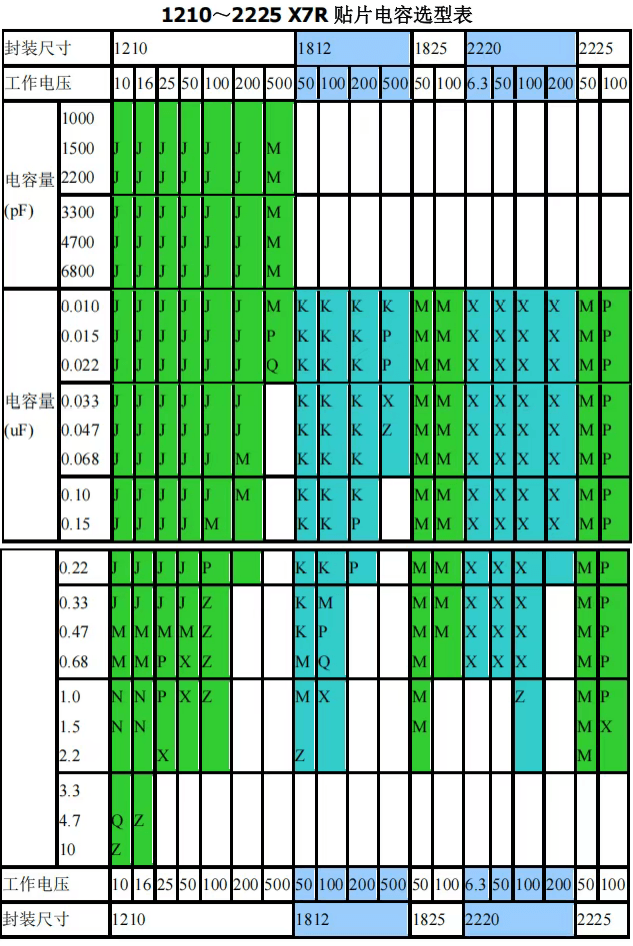
- 2225 and 2220 ultra-large packages support up to 10μF large-capacity X7R capacitors, which are prioritized for high-voltage power input filtering;
- Low-voltage specifications of 6.3V only exist in 1825/2220 packaging, and can be selected as needed for low-voltage high-power circuits powered by batteries;
- Large-thickness Z/Y/X type capacitors have higher capacity limits, but if the product has a housing height limit, a thin version with multiple parallel capacitors of the same capacity can be used instead.