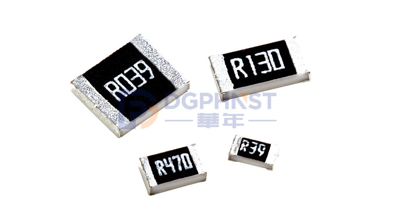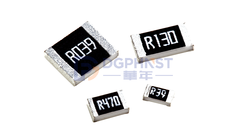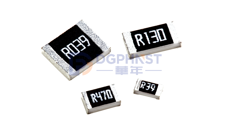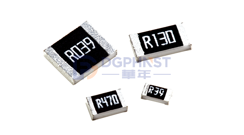
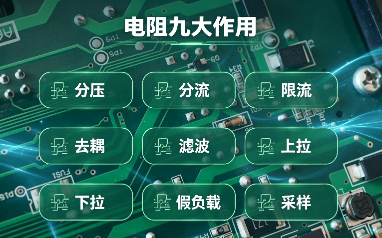
From indicator lights and microcontroller pins to power supplies and driver circuits, resistors are present in almost all electronic devices. The function of resistors goes far beyond merely 'blocking current.' In practical circuit design, resistors can achieve nine key functions: voltage division, current splitting, current limiting, decoupling, filtering, pull-up, pull-down, dummy load, and sampling, ensuring the safety and stable operation of circuits.
1. Voltage Division: Distributing Circuit Voltage as Needed
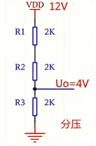
Voltage division is one of the most common functions of resistors. The core principle is series voltage division according to resistance ratio. In a circuit, when multiple resistors are connected in series, the total voltage is distributed across each resistor based on their resistance values.
In daily circuits, many components require a working voltage lower than the total power supply voltage, so they cannot be directly powered. At this point, series resistors can be used for voltage division to obtain the appropriate voltage for component use. In short, resistors can 'split' high voltages into low voltages required by the circuit, meeting the needs of different circuit components.
2. Current Splitting: Distributing Current to Protect Components
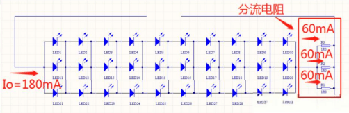
Current splitting with resistors is suitable for scenarios where the circuit current is large and a single component or resistor cannot handle the power. The core rule is parallel current splitting, where the current in a parallel circuit is inversely proportional to the resistance value. The larger the resistance, the smaller the current it carries.
In actual circuit design, parallel current-splitting resistors must have similar resistance values. If the resistance values differ too much, the resistor with a smaller resistance will carry most of the current, leading to a sharp increase in power loss, overheating, and eventually burning out the component, causing circuit failure. The essence of current splitting is to distribute large currents to avoid overloading and damaging a single component.
3. Current Limiting: Controlling Current Within Rated Range
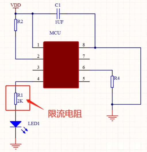
Almost all electronic components have a maximum rated operating current. Once the current exceeds this limit, the component may be damaged. Current-limiting resistors are primarily used to control the circuit current and keep it within the safe operating range of the component.
Common examples include LED indicator light circuits and small power supply indicator light circuits, which typically have a current-limiting resistor in series. After the LED is conducting, its internal resistance is very low, and without a current-limiting resistor, the current will surge immediately upon power-on, directly burning out the LED. By adding a current-limiting resistor in series, the working current of the circuit can be effectively controlled, allowing the component to operate stably within the rated range.
4. Decoupling: Eliminating Inductive Energy to Stabilize Circuits
Inductive components such as relays and motors generate reverse induced electromotive force during start and stop operations, accumulating extra inductive energy. If this energy is not released promptly, it can produce voltage spikes that interfere with sensitive components like main control chips and transistors, potentially damaging them in severe cases.
Decoupling resistors provide a dedicated discharge path for residual inductive energy, quickly consuming excess circuit energy and eliminating coupling interference and voltage fluctuations generated by components. This makes the start and stop process of inductive components smoother.

5. Filtering: Pairing with Capacitors to Purify Signals
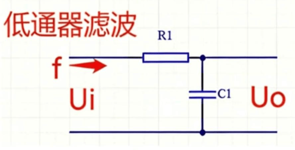
The filtering effect of a single resistor is limited. In practical applications, resistors are often paired with capacitors to form RC filter circuits, achieving signal purification. The most common example is a low-pass filter circuit.
The capacitive reactance of a capacitor is inversely proportional to the signal frequency. High-frequency interference signals can be grounded and dissipated through the capacitor. Resistors, on the other hand, can suppress the loss of low-frequency signals and DC signals, ultimately retaining stable low-frequency signals and DC voltage while filtering out noise and high-frequency interference in the circuit. This circuit is widely used in power regulation and signal noise reduction scenarios to improve the quality of voltage and signal output.
6. Pull-Up: Eliminating Floating Pins and Fixing High-Level State
In microcontroller and logic chip circuits, floating pins can be in a suspended state, making them susceptible to external interference and generating unstable parasitic voltages, which may lead to circuit misjudgment and false triggering.
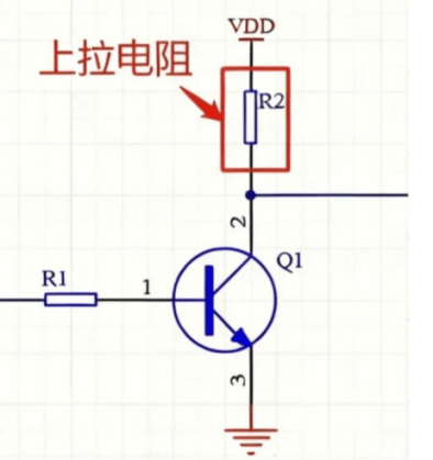
A pull-up resistor connects one end to the power supply VCC and the other end to the chip's pin. When the pin has no signal output, the resistor pulls the pin's potential up to the power supply voltage, fixing the high-level state and solving the problem of floating pins, ensuring the stability of the circuit's logical state.
7. Pull-Down: Stabilizing Low Level and Avoiding Signal Disruption
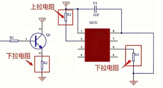
The principle of a pull-down resistor is the opposite of a pull-up resistor. One end is connected to ground, and the other end is connected to the circuit pin. It also aims to solve the issue of floating pins. When there is no valid signal input to the circuit, the pull-down resistor pulls the pin's potential down to ground level, stabilizing and locking the low level.
Pull-up and pull-down resistors act as the 'stabilizers' of digital circuits. Although simple, they can prevent signal confusion and program errors caused by floating voltages at the source. They are essential details in embedded and digital circuit design.
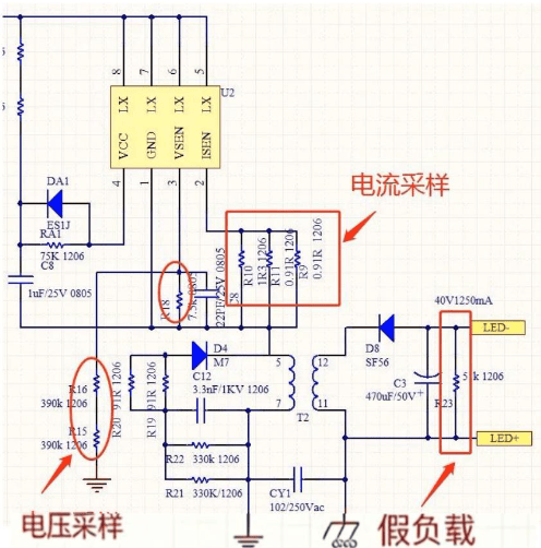
8. Dummy Load: Optimizing Power Output and Preventing No Load
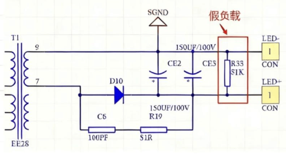
Many switch power supplies and regulated power supplies prohibit no-load operation. Under no-load conditions, the power supply output voltage becomes unstable, easily causing voltage drift and excessive fluctuations.
At this time, connecting a resistor in parallel at the power supply output forms a dummy load. It ensures the power supply remains under load, avoiding no-load operation, while also clamping and stabilizing the output voltage, making the voltage output more accurate and stable. However, it is important to note that the resistance value of the dummy load should not be too small, otherwise it would significantly increase power loss and cause the resistor to overheat and burn out.
9. Sampling: Accurately Collecting Signals for Closed-Loop Control
Smart control and precise voltage regulation in circuits rely on signal sampling, with resistors being the core component of the sampling circuit. Resistor sampling includes voltage sampling and current sampling, with the core logic being to convert various electrical signals into recognizable voltage signals and feed them back to the control chip.
For example, in constant voltage and current control of power supplies and motor speed control circuits, sampling resistors continuously collect changes in output voltage and working current, feeding the signals back to the main control unit. Based on the feedback signals, the chip adjusts the output state in real time, achieving functions such as overcurrent protection, voltage stabilization, and precise speed control through closed-loop control, which is crucial for intelligent circuit regulation.
 f600589cf644888a4d09ee035f6369.png" alt="" />