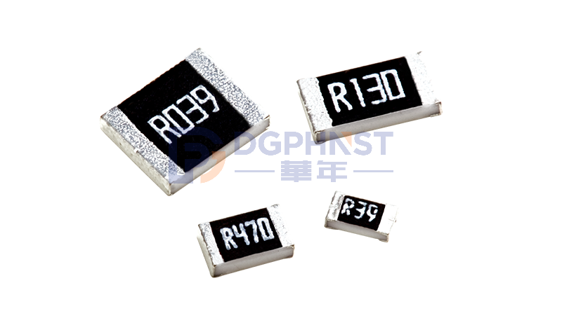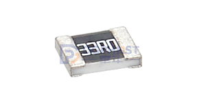
Surface mount resistors are often regarded as "simple components," with many engineers believing that identical packages can be directly interchanged. This habitual perception can easily lead to failures in later project stages.
Thick-film resistors with the same 1206 package have standard 0.25W and high-power 0.5W versions. Although their appearance and solder pads are completely compatible, they differ significantly in power handling, temperature rise, reliability, and cost. Some people fall into two extremes: either choosing 0.5W high-power resistors for convenience, increasing material costs; or using 0.25W resistors to endure high power conditions, which may cause long-term temperature rise, resistance drift, and risk of burning out.
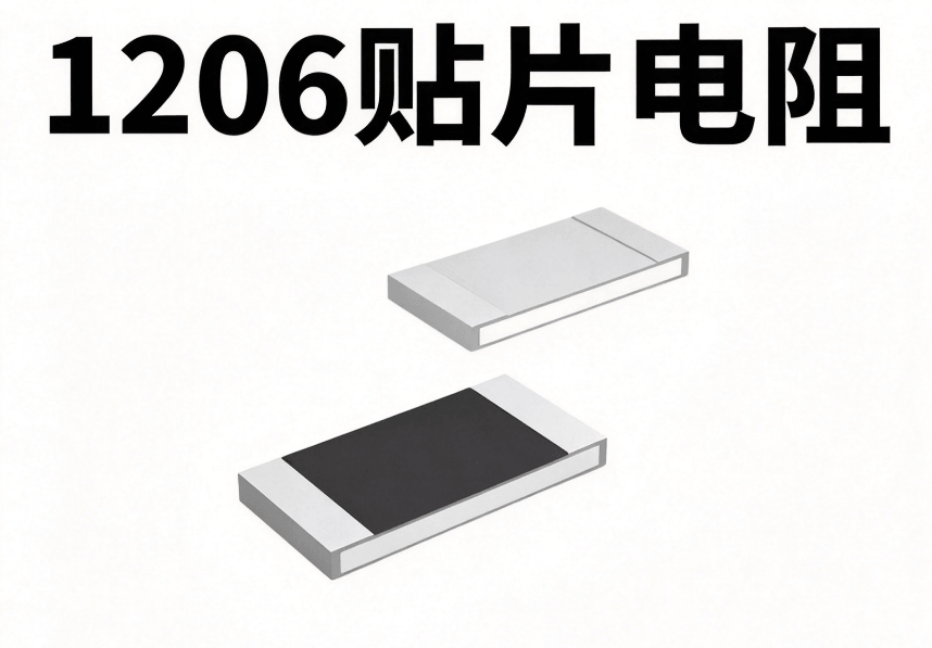
1. Same Package, Different Power: The Root of the Differences
Are the power parameters of surface mount resistors with the same package exactly the same? No.
In fact, differences in market demand and process technology allow resistors with the same package to be divided into different power levels. The core difference is not in appearance but in internal design and materials.
Taking the 1206 surface mount resistor as an example, its package defines a standardized size of 3.0mm x 1.5mm and a standard solder pad structure, used only to adapt to SMT general processing equipment, ensuring device installation compatibility and production efficiency. The package size represents only the physical shape and has no absolute relationship with power capacity, so it cannot be used as a basis for power judgment.
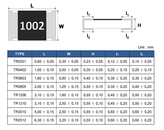
Core Differences: Different internal pastes, substrates, and electrode structures
- 0.25W: General standard thick-film resistor, industry standard specification, high cost-effectiveness
- 0.5W: High-power thick-film resistor with the same package, optimized resistor film layer and heat dissipation design to enhance power capacity
In short, standard resistors focus on balancing cost and basic performance, while high-power resistors focus on maximizing heat dissipation and power tolerance. There is no difference in appearance, and they cannot be distinguished by the naked eye. In actual R&D and production, the rated power specified in the official specification sheet must be the only criterion for judgment. When replacing materials or changing suppliers, do not rely solely on package and resistance value, but verify power parameters one by one to avoid batch quality issues caused by mixing parts and incorrect identification.
2. Typical Application Misconceptions
In actual projects, the misuse of 1206 thick-film resistor power specifications is concentrated in two extreme directions.
Misconception 1: Same package means interchangeable, using 0.25W for high power conditions
Many engineers use 0.25W resistors directly in high power circuits during debugging, assuming it works fine for short-term testing and continuing to mass production. This approach carries significant risks: resistor failure does not occur immediately, but accumulates over time due to high temperatures.
If the actual power consumption approaches or exceeds the rated power, the resistor body will heat up, causing gradual degradation of the film layer and resistance drift beyond the tolerance range. Precision sampling and voltage divider circuits may produce measurement errors, leading to product parameter non-compliance; in current limiting and load circuits, high temperatures accelerate aging and shorten device life. Under extreme conditions, the film layer may burn out, causing circuit failure.
It is necessary to distinguish between short-term pulse power and continuous rated power: if the instantaneous peak power exceeds the limit with narrow pulse width and low duty cycle, the resistor can withstand it; however, for continuous DC or high duty cycle power, the rated power must be strictly followed, and the pulse tolerance capability should not be used to assess continuous operation performance.
Misconception 2: Higher power margin is better, all circuits use 0.5W
This is a common "conservative design" misconception: thinking that using higher power resistors can avoid power-related failures. While this approach solves the risk of insufficient power, it also causes multiple hidden problems.
Firstly, it increases material costs. The price of 0.5W high-power resistors is 30% to 50% higher than that of 0.25W standard resistors of the same resistance value and precision. For mass production in consumer electronics and home appliances, even a small price difference per component can result in a significant cost gap when multiplied by millions of units, reducing product price competitiveness.
Secondly, some high-power resistors have modified internal structures, resulting in deviations in parasitic inductance and capacitance compared to standard models, which may interfere with signals in high-frequency circuits. Additionally, using a unified high-power specification for all products reduces the reusability of standard materials, increases material management, inventory, and BOM management complexity, creating unnecessary performance redundancy.
3. Core Criteria for Specification Matching
The key to properly matching resistor power specifications is to comprehensively evaluate based on actual circuit conditions from three dimensions: actual power consumption, ambient temperature, and application scenario, ensuring long-term stable operation of the component.
1. Calculate Actual Power Consumption First, Follow Derating Design
Resistor power consumption can be calculated using the formula P = I²R = U²/R. It is essential to follow derating usage standards in hardware design, which is crucial for reliable operation of the component.
In the industry's general standard, the continuous working power of a 0.25W standard thick-film resistor must be controlled within 0.125W, implementing a 50% derating. The continuous power consumption of a 0.5W high-power resistor should not exceed 0.25W. This derating standard considers factors such as temperature fluctuations, component parameter variations, and long-term aging, providing sufficient power margin for the resistor's entire lifecycle.
2. Consider Ambient Temperature and Thermal Coupling Effects
- High-temperature environments (≥70°C): Resistor power will be derated. The higher the temperature under the same power consumption, the more likely you need to choose a higher power specification.
- Close to heat-generating components (MOS, power chips): Prefer the 0.5W high-power version to reduce the risk of failure caused by thermal coupling.
3. Scenario Comparison Table
|
Specification |
Recommended Application Scenarios |
Not Recommended Scenarios |
|
1206 0.25W Thick-film Resistor |
General signal sampling, voltage division, small current limiting, room temperature environment, low power consumption, mass-produced consumer electronics |
Continuous high power, high-temperature enclosed environments, close to heat sources |
|
1206 0.5W High-power Thick-film Resistor |
Power circuits, BMS sampling, industrial control boards, enclosed enclosures, high-temperature environments, requiring greater power margin |
Simple low-voltage small signal circuits (Cost waste) |
4. Notes on Replacing Different Power Specifications
Due to the complete compatibility of the 1206 package, resistors with different power ratings are often replaced in projects, but the replacement process needs to be carried out in a standardized manner to avoid design hazards. The following are specific notes to consider.
First, the packaging process is fully compatible. Resistors of different power levels follow the same industry standard, with consistent package size and PCB solder pad specifications, allowing direct replacement without adjusting the stencil or processing program for SMT placement. Due to the ease of replacement, R&D personnel may overlook the power parameter differences, leading to design risks.
Second, thoroughly check electrical parameters. Replacement should not only check resistance value and rated power, but also confirm key parameters such as resistance accuracy level, temperature coefficient, and voltage rating. The specifications of resistors with the same resistance value but different power levels may have deviations, especially in precision sampling circuits, where temperature coefficient deviation can directly affect measurement accuracy. When replacing, strict verification is required to avoid introducing measurement errors.
Third, distinguish between pulse power and DC rated power. For circuits with short-term impulse pulses, do not determine compatibility based on average power consumption alone. Instead, refer to the pulse power curve in the component specification sheet and conduct a comprehensive assessment based on pulse width, duty cycle, and peak power. In cases with narrow pulse width and low duty cycle, resistors can tolerate higher peak power; however, for long pulses and high duty cycles, calculations should be based on DC continuous power consumption.
In Conclusion
Choosing surface mount resistors cannot use package size as the sole criterion. The power differences of resistors with the same package are determined by internal processes and material structures, not external appearances.
For general voltage division and small signal circuits, the 0.25W resistor is preferred for its higher cost-effectiveness. For high-temperature enclosed environments, close to heat sources, and high continuous power consumption scenarios, the 0.5W resistor is recommended to provide adequate power margin.