
In BMS current sampling design, calibration circuits completed at room temperature can achieve measurement accuracy within 0.5%. However, under high-temperature conditions such as summer enclosed engine compartments or energy storage cabinets running at full power, significant deviations appear in SOC estimation accuracy.
Upon teardown investigation, parameters of core components like ADCs and op-amps remain unchanged, and nominal resistance values meet specifications. The issue typically stems from an often-overlooked parameter: the Temperature Coefficient of Resistance (TCR).
1. What Exactly Does TCR Describe?
TCR describes how much the resistance value changes relatively for every 1°C change in temperature. The unit is ppm/°C, meaning parts per million per degree Celsius.
Calculation Formula:
TCR = (R2 − R1) / [R1 × (T2 − T1)] × 10⁶ (Unit: ppm/°C)
Where R1 is the resistance value at the reference temperature (typically 25°C), and R2 is the resistance value at the target temperature.
1 ppm = 0.0001%, i.e., one part per million.
A TCR of ±50 ppm/°C means that for every 1°C change in temperature, the resistance value changes by no more than ±0.005%.
Resistance variation with temperature is an inherent physical property of materials: rising temperatures intensify lattice vibrations within the material, altering carrier scattering levels, which ultimately leads to resistance drift; when the temperature returns to the baseline, the resistance also recovers synchronously.
TCR is not about precision itself, but rather the fact that "as soon as the temperature changes, the sampling baseline shifts."
2. Focusing Only on Nominal Accuracy Cannot Cover Operating Temperature Errors
Calibration at room temperature can eliminate initial resistance errors but cannot offset the impact of temperature drift.
How wide is the BMS operating temperature range? From -40°C cold start to 85°C continuous high-current operation, plus self-heating caused by the resistor's own power dissipation, the actual temperature of the sampling resistor in operational conditions may jump from 25°C to over 80°C.
Under these conditions: A resistor with ±1% nominal accuracy can maintain errors within 1% at room temperature. However, if the TCR is ±200 ppm/°C, the drift caused by a 60°C temperature rise is 200 × 60 = 12,000 ppm = 1.2%. This indicates that temperature drift alone exceeds the initial accuracy specification.
Texas Instruments (TI) explicitly states in its application notes for BMS current sensing: Sampling resistors should be selected from models with a TCR within 50 ppm/°C to minimize the impact of temperature changes on current measurements.
3. Alloy Resistors vs. Thick-Film Resistors: How Large Is the TCR Gap?
TCR metrics vary significantly across different resistor materials. The typical TCR ranges, material characteristics, and suitability for BMS scenarios are shown in the table below:
| Resistor Type | Typical TCR Range | Material Characteristics | BMS Suitability |
| Manganin/Copper-Manganese Alloy | ±10~±50 ppm/°C | Low-drift alloy, stable lattice structure | Suitable for high-precision current sampling scenarios |
| Alloy Sampling Resistor (General) | ±25~ ±100 ppm/°C | Alloy foil body, high power density | Mainstream application solution for BMS |
| Thick-Film SMD Resistor | ±100~±500 ppm/°C | Ceramic substrate + thick-film paste, low cost | Suitable for medium-low temperature, non-precision scenarios |
| Standard Carbon Film/Metal Film | ±200~±1000 ppm/°C | Lower cost, poor temperature drift characteristics | Not recommended for precision current sampling |
| Copper Terminal Electrode (Reference) | Approx. 3900 ppm/°C | Copper itself has large temperature drift | For comparison reference only |
It is important to note that even within the category of alloy resistors, products can exhibit 2–3 times difference in TCR metrics due to variations in alloy formulations and manufacturing processes (etching, stamping, welding, etc.). During selection, rely on the TCR test temperature range and guaranteed values specified in the datasheet.
4. Temperature Drift Calculation Under Typical Operating Conditions
The following combines common BMS selection scenarios to illustrate the actual impact of temperature drift through specific calculations.
Assumptions:
Sampling Resistor Value: 1 mΩ (0.001 Ω)
Nominal Accuracy: ±1%
TCR: ±50 ppm/°C (typical value for alloy resistors)
Operating Temperature: Rising from 25°C to 85°C, ΔT = 60°C
Temperature Drift Amount: 50 ppm/°C × 60°C = 3000 ppm = 0.3%
Corresponding Resistance Change: 1 mΩ × 0.3% = 0.003 mΩ
This 0.3% might seem small, but if the total accuracy budget for system-level current measurement is ±0.5%, temperature drift alone consumes 60% of the error allowance. Adding op-amp gain errors, ADC quantization errors, and PCB trace parasitic resistance makes it easy for system accuracy to exceed limits.
The performance of different TCR grades under the same 60°C temperature rise is shown below:
| TCR Grade | Drift After 60°C Rise | Impact on ±0.5% Accuracy Budget |
| ±50 ppm/°C (Alloy) | 0.3% | Consumes 60% of budget; strict margin control needed when combined with other errors |
| ±100 ppm/°C (High-end Alloy) | 0.6% | Exceeds ±0.5% budget; high risk to system accuracy |
| ±200 ppm/°C (Thick-Film) | 1.2% | Far exceeds budget; unsuitable for precision BMS sampling |
| ±800 ppm/°C (Standard Resistor) | 4.8% | Fails to meet basic requirements for precision sampling |
In high-current applications, self-heating effects of the resistor must also be considered. Continuous high current passing through milliohm-level sampling resistors causes additional resistance drift due to self-heating. If PCB thermal design is insufficient, copper foil current-carrying area does not meet standards, or the resistor is adjacent to heat-generating components like MOSFETs or inductors, the actual temperature rise will exceed theoretical values, increasing temperature drift errors accordingly.
5. Common Pitfalls in Sampling Resistor Selection
Pitfall 1: Looking Only at Nominal Accuracy, Ignoring TCR Grade
Many people select components based solely on finding ±1% accuracy in the datasheet, glancing briefly at TCR without careful review. The result is accurate calibration at room temperature but system drift at high temperatures. Remember: Accuracy determines "how correct it is out of the factory," while TCR determines "whether it remains correct when temperature changes." Both metrics must be evaluated.
Pitfall 2: Assuming All "Alloy Resistors" Have Low Temperature Drift
While alloy resistors generally have lower TCR than thick-film types, differences between series can be substantial. For example, Walter’s PMSH series alloy sampling resistors cover a TCR range of ±50 to ±350 ppm/°C, a span of nearly 10 times. Before selection, check the specific model’s TCR guaranteed values and test conditions; do not use series averages as design basis.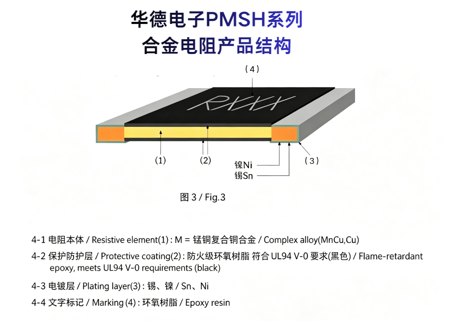
Pitfall 3: Ignoring the Impact of PCB Layout and Heat Dissipation on Actual Temperature Rise
TCR is a parameter of the resistor itself, but in actual operating conditions, the resistor's temperature rise comes not only from ambient temperature but also from its own power dissipation. Insufficient PCB copper foil area, poor thermal paths, and placing resistors close to heat-generating elements like MOSFETs or inductors cause actual temperature rises far exceeding expectations. Even low-TCR resistors suffer reduced effectiveness if paired with poor thermal management.
Conclusion
Returning to the initial question: How important is TCR?
Factory accuracy determines the resistor's baseline correctness at room temperature, while TCR determines resistance stability under wide-temperature operating conditions. In applications like BMS, which feature wide operating temperature ranges and large dynamic current ranges, TCR is typically one of the primary consumers of the system accuracy budget.
Shunhai Technology is an authorized distributor for Walter Electronics and also distributes alloy products from brands such as TE Connectivity, Sunway, Milliohm, and Lixing. We provide selection support for BMS sampling chains, sample requests, and datasheet lookup services. To match specific models, please provide parameters such as current range, accuracy requirements, and operating temperatures.