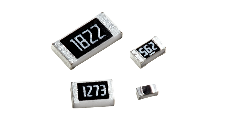
PCB space is continuously shrinking while system power requirements increase. A single SMD resistor occupies only a few square millimeters but must sustain several watts of power dissipation long-term, maintaining stability across a wide temperature range from -55°C to 155°C.
Industry statistics indicate that approximately 12% of failures in industrial electronic systems are related to passive resistive components. The three primary causes are overpower burnout, resistance drift under high temperatures, and pulse shock failures. This presents a common challenge for the thick film resistor industry: how to break through power density limits without changing standard packages.
I. Three Major Limitations of Standard Thick Film Resistors
1. Nominal Power Rating is at "70°C Ambient", but Actual Operating Conditions are Harsher
Enclosed chassis, component stacking, and proximity to heat-generating elements can easily push the ambient temperature around resistors above 100°C. Without sufficient derating margin, prolonged operation at high temperatures accelerates paste aging, causing resistance drift far exceeding expectations. Industry best practices recommend retaining at least 30% power margin for industrial scenarios and over 50% for automotive projects.
2. Pulse Loads Have Destructive Effects Far Exceeding Continuous Power Dissipation
Short-duration pulses such as capacitor charging surges during power-on, IGBT switching spikes, and motor startup impacts can have energy peaks several times higher than continuous power ratings. Standard thick film resistors typically do not specify pulse withstand capability, leading to latent failures where "average power meets specs, but peak loads cause failure," making troubleshooting extremely difficult.
3. Miniaturization Forces Upgrades in Power Density
Taking the 2512 package as an example, 1W was sufficient for most applications five years ago; today, 2W has become the baseline requirement for medium-to-high power circuits. "Double the power in the same package" has shifted from a selling point to a necessity.
II. Three Technical Routes for High-Power Thick Film Resistors
Facing the challenge of power density, there is no unified answer in the industry; different manufacturers have pursued different technical paths. These can generally be categorized into three directions.
Route 1: Material System Upgrade
This approach maintains the thick film process framework but strengthens the substrate, paste, and electrodes—using high-purity alumina substrates to improve thermal conductivity, optimizing ruthenium-based pastes to enhance load endurance, and employing three-layer termination electrodes to boost high-current capacity and soldering reliability. This solution is fully compatible with standard EIA packages; replacing materials requires no PCB redesign, stencil changes, or SMT program adjustments. The CRH series resistors distributed by Shunhai Technology fall into this category.
Route 2: Package Structure Innovation
Solutions such as double-sided heat dissipation or power packages with heat sinks can further increase power density by an order of magnitude. However, these non-standardized sizes require layout redesigns and incur higher costs, making them suitable primarily for applications like energy storage converters.
Route 3: Transition to Alloy Resistor Technology
For milli-ohm level high-current sensing applications, thick film technology faces physical limitations. Alloy resistors, with their lower TCR and stronger impact resistance, become the superior choice. However, they do not offer advantages in resistance value coverage or cost, serving as a complement rather than a replacement for thick film technology.
For the next 2-3 years, the mainstream direction remains "Standard Package + Material Upgrade." For B-end customers, the validation cost of a single PCB revision can exceed the value of the resistors themselves by hundreds of times.
III. Tianer CRH Series: Power Breakthrough Within Thick Film Technology
While standard 2512 package thick film resistors typically have a rated power of around 1W, the CRH series achieves a stable 2W in the same package, doubling the power density. This core improvement stems from three process enhancements:
First, high-purity alumina substrates, which have approximately 30% higher thermal conductivity than conventional substrates, efficiently transfer heat to PCB pads to control temperature rise;
Second, optimized sintering formulas for ruthenium-based pastes, resulting in lower resistance drift after 1000 hours of continuous full-load operation, suitable for unmanned industrial equipment and communication base stations;
Third, three-layer termination electrodes with nickel barrier layers and pure tin plating, which enhance high-current passing capability while improving oxidation resistance and mechanical connection reliability, adapting to automotive and industrial control environments with frequent vibration and temperature fluctuations.
The 2W rating refers to continuous power at a substrate temperature of 70°C, not short-term peak power. Above 70°C, linear derating according to the curve is required, dropping to zero at 155°C. It is recommended to keep actual long-term working power within 70% of the rated value.
The CRH series covers all standard packages from 0402 to 2512, with each package size offering one grade higher power rating than the conventional CR series:
| Package | Metric Size | CRH Rated Power | Typical Application Scenarios |
| 0402 | 1.0×0.5mm | 0.1W Class | Miniaturized signal circuits, auxiliary current limiting |
| 0805 | 2.0×1.25mm | 0.25W | Consumer electronics, small board circuits |
| 1206 | 3.2×1.6mm | 0.5W | Power management, home appliance main control boards |
| 1210 | 3.2×2.5mm | Approx. 0.66W | Industrial control drives, servo auxiliary circuits |
| 2512 | 6.35×3.2mm | 2W | Switch-mode power supplies, inverters, automotive low-voltage circuits |
In terms of precision, two mainstream options are provided: ±1% (F Grade) and ±5% (J Grade). Temperature coefficients cover ±100ppm/°C and ±200ppm/°C, with an operating temperature range of -55°C to +155°C, basically meeting industrial-grade and automotive wide-temperature requirements.
From a product positioning perspective, CRH has clear boundaries: it is a standardized product line using thick film technology to resolve the contradiction between "small package, high power consumption." If your application involves BMS high-current sampling, choose alloy resistors; if you need high-precision voltage divider references, choose thin film resistors; however, for current limiting, discharge, and load circuits ranging from a few ohms to mega-ohms where PCB area is sensitive, high-power thick film resistors like CRH represent the optimal balance of performance and cost.
IV. Scenario-Based Selection Key Points
1. Switch-Mode Power Supplies: CRH resistors are often used in input current limiting, startup resistors, RCD snubbers, and output dummy loads. Attention must be paid to whether power-on surges exceed pulse withstand limits and the actual ambient temperature around the resistor under full load. During layout, it is recommended to reserve ample copper foil area beneath the pads for heat dissipation.
2. Industrial Control: Scenarios such as PLC analog voltage division, inverter IGBT gate drive current limiting, and servo signal conditioning involve large temperature swings and long operational cycles. For voltage division and sampling, select F-grade (±1%) resistors; for general current limiting and loads, J-grade (±5%) resistors suffice. Chassis ventilation is often limited and prone to heat accumulation, requiring more conservative derating compared to consumer electronics.
3. New Energy Vehicles: Applications such as OBC auxiliary circuits, headlight drivers, and body control units must meet AEC-Q200 reliability standards in addition to electrical performance. The automotive-grade version of CRH features specialized enhancements for vibration, thermal cycling, and high-temperature/high-humidity conditions.
4. Communication Base Stations: Systems such as 48V power supplies and amplifier board load circuits operate uninterruptedly for 24 hours, with high downtime costs. Stringent requirements exist for long-term aging characteristics, where the low-drift advantage of CRH becomes increasingly apparent during continuous operation.
Conclusion
The higher the system complexity, the greater the weight of basic component reliability. The failure of a resistor costing mere cents can halt thousands-of-dollars equipment or even stop production lines. Selection is not about choosing "parameters just barely adequate," but rather ensuring "sufficient margin remains within operating condition boundaries."
With the same 2512 package, running a conventional 1W product at full load versus a 2W CRH product carrying half the load results in significantly different long-term reliability. For the same power requirement, a conventional solution might need two resistors in parallel, whereas a single CRH resistor suffices, offering better BOM cost and layout area efficiency.