Installation method and precautions for self recovering fuses (PPTC)
1、 Typical installation method
PCB soldering integration
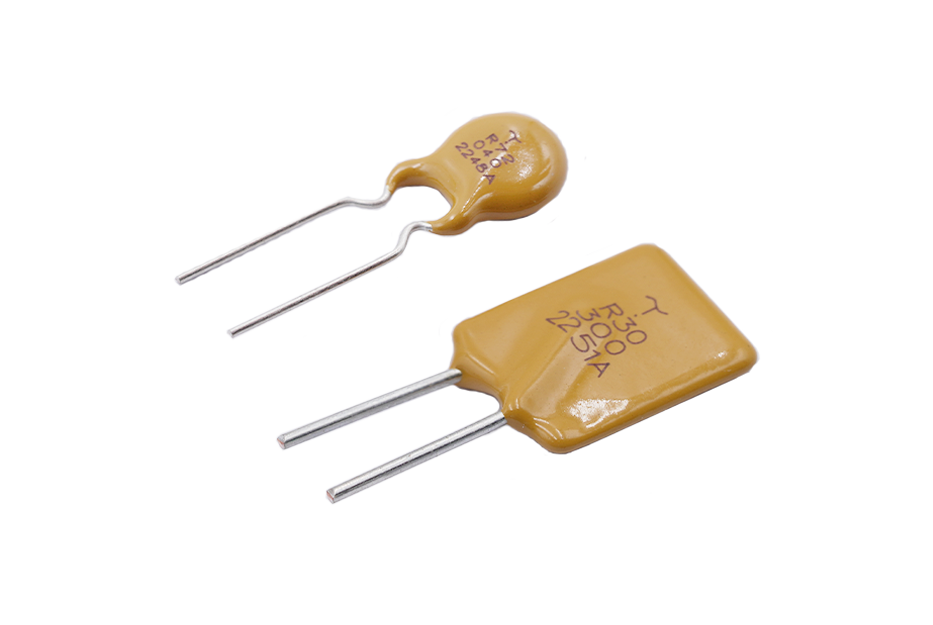
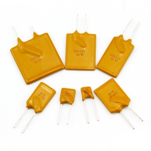
(1) Direct insertion packaging (such as radial leads)
Adopting through-hole soldering technology, suitable for double-sided PCB layout
Suggest reserving a lead length of 35mm to avoid thermal stress damage
The installation direction should maintain a safe distance from the surrounding heating elements
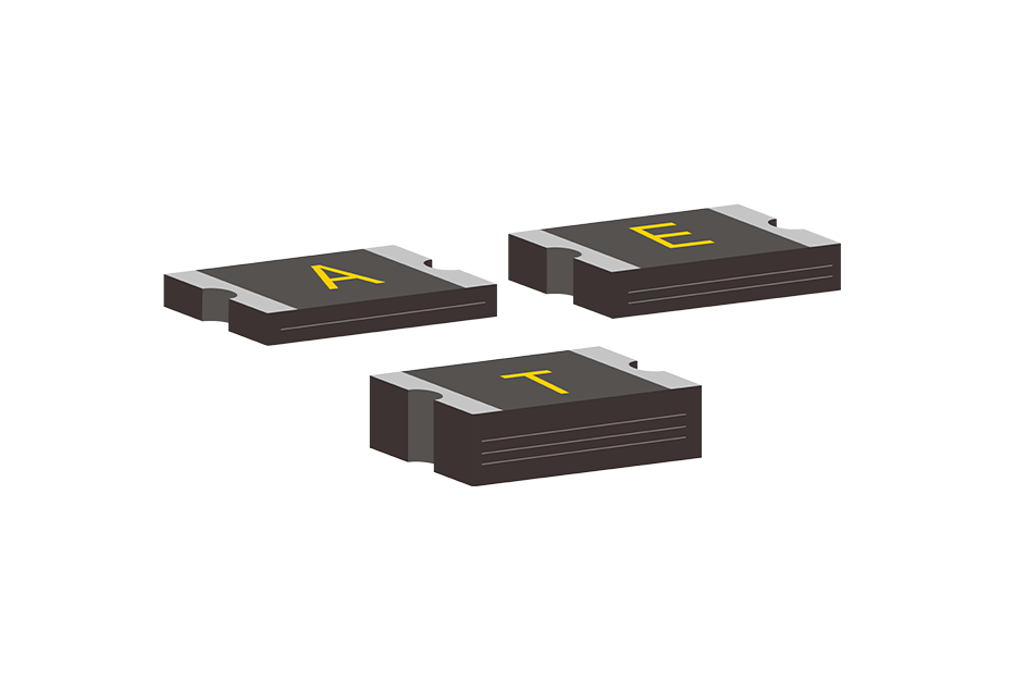
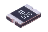
(2) Surface mount packaging (SMD type)
Priority should be given to using reflow soldering technology, and the temperature curve should comply with the device specifications
Pad design should follow the heat capacity requirements in the device manual
A moisture-proof isolation zone needs to be set up to avoid residual soldering flux
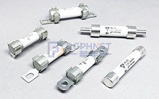
Terminal type wiring installation
(1) Wire harness series connection method
When using crimping terminals, it is necessary to ensure that the contact area is ≥ 1.5 times the wire diameter
Suggest using circular terminals with anti loosening screws for fixation
Multiple strands of wire need to be tinned to prevent loose threads
(2) Equipment level installation
Set up dedicated installation brackets inside the distribution box
Maintain a vertical installation posture to optimize heat dissipation
It is recommended to install an arc extinguishing device at the power input end
2、 Special scenario configuration plan
Multi channel parallel topology
Need to configure a current sharing resistor (recommended resistance of 0.10.5 Ω)
Parallel devices should maintain a temperature difference of ≤ 2 ℃
The layout should ensure symmetrical routing length
Installation in high temperature environment
Fill the gap between the device and the heat sink with thermal conductive adhesive
The installation location should avoid the active heat source radiation area
Suggested derating use (15% derating for every 10 ℃ increase in temperature)
3、 Key points of engineering practice
Space layout criteria
Maintain a distance of ≥ 10mm from the electrolytic capacitor
Prohibit parallel installation of high-power inductive components
The length of the detection end wiring should be ≤ 30mm
Reliability enhancement measures
Control pressure ≤ 2MPa during secondary injection molding packaging
The vibration environment requires the addition of silicone shock absorbers
Three proof paint should be applied in humid environments (avoiding electrode areas)
4、 Verification process after installation
Basic parameter testing
DC impedance measurement at room temperature (compared to nominal value ± 20%)
Insulation resistance test (≥ 100M Ω/500VDC)
Functional verification
Overcurrent trigger time test (1.5 times rated current ≤ 60s)
Recovery characteristic detection (impedance recovery of 90% within ≤ 60 seconds after power failure)
5、 Common installation misconceptions
Wrong selection
Mistakenly using the holding current as the trigger current parameter
Neglecting the impact of voltage drop on the system
Process defects
When manually soldering, the contact time of the soldering iron is greater than 3 seconds
Use highly corrosive solvents during cleaning
system matching
Without considering the surge characteristics of capacitive loads
No delay is set when used in conjunction with mechanical circuit breakers
Note: Specific installation requirements should be based on the device specifications. It is recommended to conduct thermal simulation analysis and actual operating condition testing before implementation.