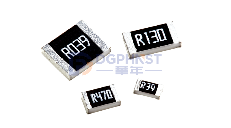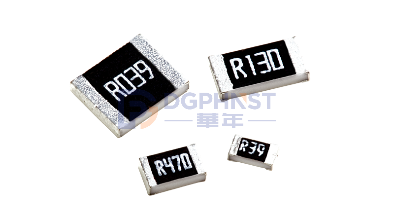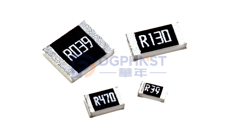
As the fundamental building block of electronic circuits, resistors may look tiny, yet they are widely applied in consumer electronics, new energy vehicles, industrial control, AI servers and many other fields. They are indispensable core basic components for the electronics industry.
Statistics show that China’s domestic resistor market size exceeded 32 billion RMB in 2025 and is expected to reach 35 billion RMB in 2026. The global market scale is over 100 billion RMB. Among all product categories, high-end and automotive-grade resistors see a growth rate far above the industry average.
We use electronic devices every day, but most people know little about resistors. Starting with basic knowledge, this article will elaborate on core theories of resistors step by step, helping you understand circuits and electronics.
Basic Principles & Key Parameters of Resistors
When a circuit is powered on, free electrons inside conductors flow in a fixed direction. During movement, electrons constantly collide and rub against conductor atoms and internal impurities, which hinders electric current. This physical property is resistance, and it is the fundamental principle for resistors to ensure normal circuit operation.
For circuit practice, component selection and troubleshooting, three core parameters determine resistor performance. Their functions are as follows:
-
Resistance ValueIt indicates a resistor’s ability to block current. The basic unit is ohm (Ω), and common derived units include kiloohm (kΩ) and megaohm (MΩ). Resistance value is the primary reference for selecting and replacing resistors.
-
Power RatingIt refers to the maximum power consumption a resistor can withstand during long-term stable operation, measured in watt (W). If a resistor with insufficient power rating is used, it will overheat continuously, accelerate aging, or even burn out completely and cause circuit failure.
A resistor’s allowable power load is closely related to ambient temperature, which can be illustrated by the load curve. In the figure: P stands for allowable power, P<sub>R</sub> for rated power, t<sub>R</sub> for rated ambient temperature, t<sub>min</sub> for minimum ambient temperature and t<sub>max</sub> for maximum ambient temperature.
As shown in the curve: when the ambient temperature is lower than the rated temperature, the allowable power P equals the rated power P<sub>R</sub>. Once the temperature exceeds t<sub>R</sub>, the allowable power drops sharply. Therefore, resistors are prone to burnout under high temperatures.
- Tolerance
It represents the deviation between the actual resistance and the marked value. The smaller the tolerance figure, the higher the resistance accuracy and the more stable the circuit. High-precision resistors are mandatory for precision circuits.
Common Types of Resistors
Classified by material, structure and application scenarios, mainstream resistors in the industry fall into five categories. Click the blue link for more details: Practical Guide | Differences Between Metal Film Resistors and Other Common Resistors (with comparison table & internal structure diagram)
- Carbon Film Resistor: Easy to manufacture, cost-effective with a full range of resistance options. A traditional general-purpose type.
- Metal Film Resistor: Adopts thin metal layer as the conductive part. It features high resistance accuracy, low temperature drift and low operating noise, with overall performance superior to carbon film resistors.
- Wirewound Resistor: Made by winding special resistance wire. It can carry large current, withstand impact and endure extremely high temperatures.
- SMD Resistor: A surface-mount component with compact size. It fits automated production and helps make circuit boards more compact.
- Special Resistor: Mainly includes thermistors, varistors and photoresistors. Their resistance values change with external conditions such as temperature, voltage and light.
Identification of Resistor Parameters
Whether for component procurement, circuit maintenance or part replacement, you can quickly read parameters via markings on resistor surfaces. There are two main identification methods: color bands for through-hole resistors and digital codes for SMD resistors.
1. Color Band Resistors
This marking method is used for traditional through-hole resistors. Different combinations of color bands indicate resistance value and tolerance. Four-band and five-band resistors are the most common, widely used in legacy circuits and mainboards of industrial equipment.
Color code reference:
Black=0, Brown=1, Red=2, Orange=3, Yellow=4, Green=5, Blue=6, Violet=7, Gray=8, White=9, Gold=±5%, Silver=±10%, No band=±20%
2. SMD Resistor
Ordinary small SMD resistors are generally marked with 3-digit or 4-digit numbers. 3-digit codes correspond to ±5% tolerance, while 4-digit codes correspond to ±1% tolerance. High-precision SMD resistors are printed with full resistance values for easier reading and selection.
Resistance Unit Conversion
Ω = Ohm
kΩ = Kiloohm = 1,000 Ω
MΩ = Megaohm = 1,000,000 Ω
(1) 3-Digit Marking Rule
The first two digits stand for significant figures, and the last digit represents the power of 10.
Example: 103 = 10 × 10³ = 10 kΩ
(2) 4-Digit Marking Rule
The first three digits stand for significant figures, and the last digit represents the power of 10.
Example: 1002 = 100 × 10² Ω = 10 kΩ
(3) Marking with Letter R
The letter R acts as the decimal point.
Example: 10R0 = 10.0 Ω (also marked as 10Ω; the trailing 0 denotes a ±1% precision resistor, i.e. 10.00 Ω)
(4) E-96 Standard Code
In the E-96 coding system, the trailing letter represents the multiplier (e.g. A = 10⁰, B = 10¹). Refer to the corresponding table for full rules. The preceding numbers are resistance codes rather than direct resistance values.
Resistor Selection Guidelines
Main Application Functions
- Current Limiting & Protection: Restrict current in circuit branches to prevent overcurrent from damaging delicate components such as chips, LEDs and sensors. It is the most basic protection design in circuits.
- Voltage Division: Split the total circuit voltage into multiple levels to supply appropriate voltage for various components and functional modules on PCBs, ensuring coordinated operation.
- Current Shunting: Mostly used in parallel circuits. It distributes current reasonably across branches to balance load, avoid overcurrent on single lines and keep the whole circuit running steadily.
- Impedance Matching: Applied in communication and analog signal circuits. Resistors realize impedance matching to reduce signal loss, reflection and interference, and guarantee stable signal transmission.
Selection & Installation Rules
When designing circuits, replacing parts or repairing equipment, select and install resistors according to actual working conditions and standard operating procedures to minimize faults:
- Strictly Match Resistance Value: When replacing resistors, prioritize products with exactly the same marked resistance. Never alter resistance arbitrarily for precision instruments and signal circuits, otherwise equipment accuracy will be affected.
- Reserve Sufficient Power Margin: The actual operating power must be lower than the rated power. For general civil and industrial circuits, reserve a power margin of 1.5 times or more, to avoid overheating, aging or burnout caused by long-term full-load operation.
- Select Types by Application Scenarios: Choose metal film resistors or high-frequency SMD resistors for high-frequency signal circuits; use wirewound resistors for high-current and high-power scenarios; pick high-precision resistors with low temperature drift for outdoor and industrial environments with drastic temperature changes.
- Standardize Installation & Layout: Resistors generate heat during operation. Keep a safe distance from heat-generating components (power transistors, capacitors) and flammable insulating materials. Arrange components reasonably on high-density PCBs to reserve heat dissipation space and avoid local heat accumulation.
Conclusion
Nowadays, electronic devices are developing towards miniaturization, integration and automation, driving the evolution of resistor application forms. Traditional bulky through-hole resistors are gradually phased out. Thanks to small size, compatibility with automated production and high integration, SMD resistors have become the preferred choice for various terminal electronic products.
Meanwhile, the market sets higher requirements for circuit accuracy and operational stability, leading to growing demand for resistors featuring high precision, compact size, high temperature resistance and high reliability. At present, domestic manufacturing technology for passive components is mature, with sufficient supply of general, mid-range and high-end resistors to meet the demands of civil, industrial, communication and other circuit applications.