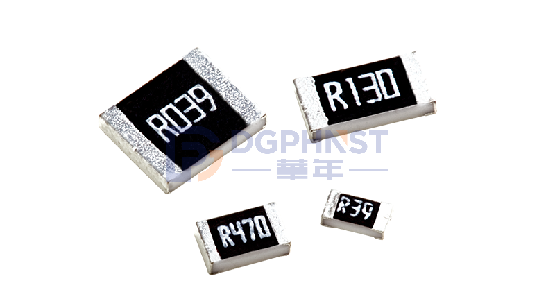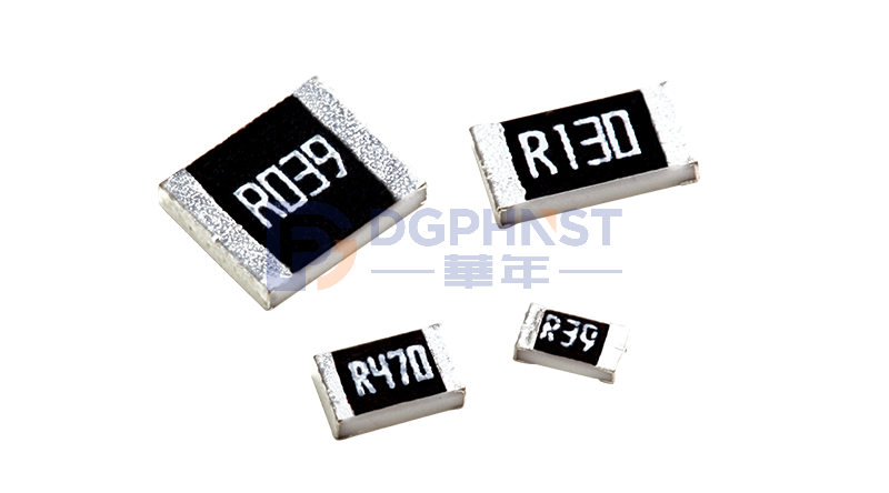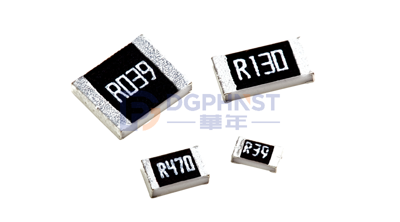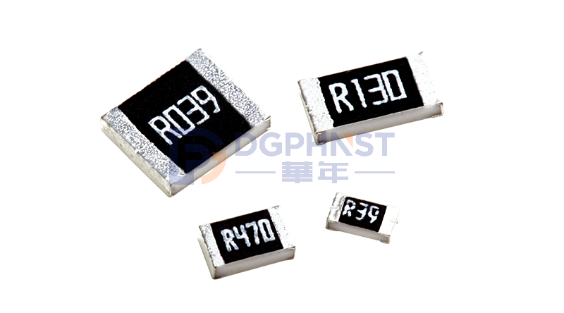
Sampling resistors play a core role in converting current and voltage in a circuit through voltage division, outputting detectable signals that can be identified by chips and instruments. They are responsible for circuit signal acquisition and real-time current and voltage detection. This article will provide a detailed introduction to sampling resistor knowledge.
Two Major Categories of Sampling Resistors
According to actual usage purposes, sampling resistors are divided into two types: current sampling resistors and voltage sampling resistors, with significant differences in resistance range, structure, and application scenarios:
Current Sampling Resistor
Installed in the equipment load circuit, it calculates the circuit current based on the voltage difference across the resistor. It comes in two packages:
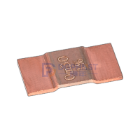
- Four-terminal Current Sampling Resistor: Resistance range is 0.01Ω~1Ω, high measurement accuracy, low temperature drift, mainly suitable for large current detection scenarios;
Four-terminal Current Sampling Resistor
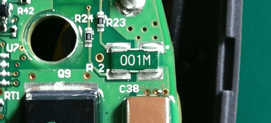
- Two-terminal Current Sampling Resistor: Resistance range is 10Ω~100Ω, simple structure, lower production cost, commonly used in small current measurement circuits.
Two-terminal Current Sampling Resistor
Voltage Sampling Resistor
A voltage sampling resistor is a resistor used to measure the voltage in a circuit. It is usually placed in the circuit being measured, calculating the voltage by measuring the voltage difference across its ends. Common types include voltage divider resistors and current-limiting resistors:
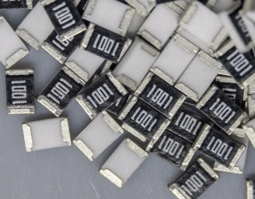
- Voltage Divider Resistor: Resistance range is 1kΩ~10kΩ, simple structure, high measurement accuracy, specifically used for precise voltage acquisition;
Voltage Divider Sampling Resistor
- Current-Limiting Resistor: Resistance range is 0.01Ω~1Ω, wide measurement range, fast signal response, suitable for high-current and high-voltage working environments.
Current-Limiting Sampling Resistor
Core Working Principle: Signal Conversion Based on Ohm's Law
All sampling resistors operate based on Ohm's Law, with current and voltage sampling corresponding to two sets of calculation formulas:
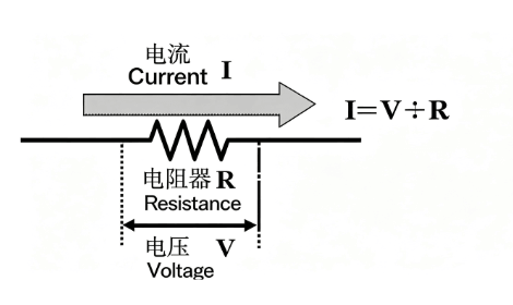
- Current Sampling Calculation: Based on the formula I=V/R, after collecting the voltage difference across the resistor, the real-time current in the circuit is calculated by combining the fixed resistance value; where V is the voltage difference across the resistor, and R is the resistance value of the resistor.
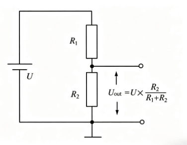
- Voltage Sampling Calculation: Using the voltage divider formula U₂=U₁×[R₂/(R₁+R₂)], the high-voltage signal is converted into a detectable low-voltage signal through resistor voltage division, calculating the total voltage being measured. Where U1 is the voltage of the circuit being measured, U2 is the voltage across the sampling resistor, R1 is the resistor in series with the circuit being measured and the sampling resistor, and R2 is the resistance value of the sampling resistor.
Application Scope and Multi-Circuit Combination Schemes
Basic Application Scenarios
Typically installed in switch power supplies, motor drive control boards, and charging adapters, they continuously monitor current and voltage to provide data support for circuit protection and power regulation.
Three Classic Combination Usage Schemes
- Current + Voltage Sampling Resistor Series/Parallel Combination: Simultaneously collect current and voltage values in the circuit to comprehensively assess the real-time operating conditions of the device;
- Series/Parallel Voltage Divider Circuit Combination: Reduce the circuit voltage to a range acceptable by the measuring chip, enabling high-voltage device testing. In the following diagram, R1 and R2 represent the resistance values of the resistors.
Voltage Divider Circuit
- Bridge Circuit: Combining two voltage divider circuits with standard sampling resistors allows high-precision measurement of unknown resistors such as thermistors, enabling extended functions like temperature detection.
Usage Precautions
The measurement accuracy and service life of sampling resistors are affected by multiple factors including selection, wiring, installation, and operating conditions. The following points should be noted during actual operation:
- The resistance value must match the actual working conditions of the circuit;
- The rated power must match the peak current of the circuit to avoid overloading and damaging components;
- The resistance value must not be too small to prevent thermal runaway and significant loss of measurement accuracy;
- In DC measurement scenarios, short-circuiting the resistor terminals is strictly prohibited;
- In AC measurement scenarios, high-temperature resistant, high-frequency low-distortion specialized models must be selected;
- Shorten the length of component leads, keep them away from high-power lines to avoid electromagnetic interference;
- Ensure secure connections without looseness to eliminate measurement errors caused by contact resistance;
- Regularly inspect aging components and replace them on time to ensure long-term stable measurement performance.
In Conclusion
Sampling resistors are basic passive components, with their core value being the realization of circuit current and voltage detection and closed-loop control. Through various combinations such as series and parallel, and bridge circuits, they can adapt to various complex circuit requirements. In practical use, details such as resistance value, power selection, wiring layout, and wiring process directly determine the measurement effect. Following usage standards ensures high-precision and stable detection performance.