In commercial and industrial (C&I) energy storage systems, current sampling in the Battery Management System (BMS) may seem like a basic step of "measuring voltage drop across a series resistor," but it directly determines SOC estimation accuracy, overcurrent protection response speed, and the safety of rack-level energy dispatching.
Overestimated current sampling leads to inflated SOC readings and distorted range judgments; underestimated sampling may miss overcurrent risks during high-rate charging and discharging. With adjustments to sampling precision metrics in new national standards and the evolution of energy storage racks toward higher power density, the selection boundaries between shunts and chip alloy resistors are being re-evaluated. Shunhai Technology outlines the technical differences and applicable scenarios of these two solutions to provide reference for BMS hardware design.
I. Measurement Objects and Precision Requirements for Energy Storage BMS Current Sampling
Current sampling in C&I energy storage systems is hierarchical, with significant differences in range and precision requirements at different levels:
| Sampling Level | Typical Range | Precision Requirement | Location |
| Battery Cluster Total Current | ±200A ~ ±500A | ±1% FS, Error ≤5A | Cluster Master Board/Busbar |
| Battery Pack/Module Current | ±50A ~ ±150A | ±0.5% | BMS Slave Board |
| Balancing Branch Current | ±1A ~ ±5A | ±1% | Cell Balancing Circuit |
| PCS Output Current | ±100A ~ ±300A | ±0.3% | PCS Controller |
According to industry requirements, battery cluster total current detection accuracy must not exceed ±1% FS, with a sampling period no greater than 50ms. After revisions to the new national standard, current sampling precision metrics have been adjusted from the original ≤0.2% to ≤2A (for ranges <200A) or ≤1% (for ranges ≥200A).
Relaxed metrics do not mean simplified selection—SOC estimation involves integrating current, so sampling errors accumulate over time. Daily SOC deviation can expand from 0.5% to over 1%. Therefore, the core of selection lies in balancing power consumption, precision, size, and cost.
II. Technical Differences Between Shunts and Alloy Resistors
Shunts and chip alloy resistors share the same measurement principle, based on Ohm's Law, inferring current by detecting the voltage drop across a series resistor. The difference lies in material form, power rating, and mounting method.
1. Manganin Shunt
The body of a traditional shunt is a manganin alloy strip, with pure copper terminals crimped at both ends, fixed to the busbar via bolts. A standard output of 75mV (or 50mV/100mV) corresponds to full-scale current.
Main Features:
Low Temperature Drift: Manganin alloy TCR is approximately ±5~±20ppm/°C; precision shunts can achieve ±2.5ppm/°C within the 0-70°C range, offering good long-term stability;
Large Range: Single specifications cover 50A to 3000A; for high-current scenarios above 500A, shunts are the primary choice;
High Precision: Combined with dedicated sampling chips, system-level precision can reach ±0.1%~±0.2%;
Low Cost: For the same range, shunt solutions are an order of magnitude cheaper than Hall sensors.
Limitations:
Higher Continuous Power Consumption: For example, a 300A range with 75mV output results in approximately 22.5W continuous power per unit; heat generation must be considered in structural design;
Larger Footprint: Bolt mounting plus copper terminals occupy PCB space, requiring specific busbar wiring designs;
No Electrical Isolation: Sampling on the high-potential side requires isolation amplifiers, increasing BOM costs;
Complex Assembly: Cannot be surface-mounted, relying on fasteners for connection.
2. Chip Alloy Resistor
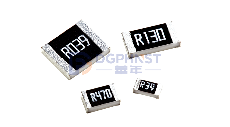
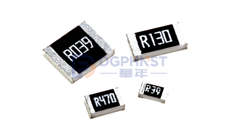
Chip alloy resistors (Current Sense Resistors) stamp nickel-chromium, copper-manganese, or iron-chromium alloys into resistive bodies, with copper electrodes welded at both ends, using standard SMD packages directly reflow-soldered onto the PCB.
Main Features:
High Board-Level Integration: The 2512 package occupies about 6.3mm × 3.2mm, consistent with standard chip resistors;
Low Parasitic Inductance: The flat structure of alloy body plus copper terminals allows inductance values in the nH range, suitable for high-frequency switching power supply sampling;
Fast Response Speed: Bandwidth can reach MHz levels, with overcurrent protection trigger delays lower than shunt solutions;
Wide Resistance Selection Range: Available from 0.5mΩ to hundreds of mΩ, offering design flexibility.
Limitations:
Limited Power Upper Bound: Standard 2512 packages have rated powers of 1W-2W; some high-power specs using thick-film technology on 96% alumina substrates have rated powers around 2W, translating to continuous currents generally not exceeding 50A-80A;
Higher Temperature Drift than Manganin: Chip alloy resistor TCR is typically ±25~±100ppm/°C;
Heat Dissipation Relies on PCB: Heat is primarily conducted through pads and copper foil; PCB layout directly affects temperature rise.
III. Key Engineering Calculations in Selection
1. Power Analysis: I²R Losses
Taking 200A continuous discharge as an example:
| Solution | Resistance | Full Voltage Drop | Continuous Power |
| Manganin Shunt (75mV) | 0.375mΩ | 75mV | 15W |
| Chip Alloy Resistor (1mΩ) | 1mΩ | 200mV | 40W |
| Chip Alloy Resistor (0.5mΩ) | 0.5mΩ | 100mV | 20W |
If the resistance value of the chip alloy resistor is selected too high, continuous power consumption may exceed that of the shunt solution. When choosing chip solutions for high-current branches, resistance values should be kept as low as possible; however, lower resistance means smaller sampling signals, placing higher demands on amplifier and ADC noise metrics—a mutual constraint.
For continuous currents exceeding 100A, prioritize shunts; below 50A, chip alloy resistors are more suitable; for the 50A-100A range, determine based on volume and heat dissipation conditions.
2. Temperature Drift Analysis: Impact of Temperature on Precision
The internal operating temperature range of energy storage cabinets is typically -20°C to +60°C; under extreme conditions, local temperatures on the BMS board may exceed 85°C.
Taking a chip alloy resistor with TCR=±50ppm/°C as an example, rising from 25°C to 85°C (a 60°C increase), the resistance drift is:
50ppm/°C × 60°C = 3000ppm = 0.3%
If the total current sampling precision budget is ±0.5%, temperature drift alone consumes 60% of the budget. Adding amplifier gain error, ADC quantization error, and PCB parasitic resistance makes it easy for system-level precision to exceed 1%.
If a manganin shunt has a TCR of ±10ppm/°C, with the same 60°C rise, the drift is approximately 0.06%, leaving a larger precision margin. This is why metering-grade applications (such as smart meters and gateway metering) universally use manganin shunts.
3. Package Derating and PCB Heat Dissipation
The rated power of chip alloy resistors is based on a 25°C ambient temperature; for every 10°C increase in actual working temperature, power must be derated by approximately 50%. A nominal 2W 2512 package may have a sustainable power of only 0.8W-1W in a 60°C environment.
When selecting chip solutions, pay attention to PCB design:
- Copper foil area of pads should be at least 2-3 times the package size;
- Use Kelvin four-wire connections for sampling traces, routing separately from the inner side of pads to the amplifier input;
- Keep resistors away from power devices and heat-generating components to reduce thermal coupling.
IV. Selection Recommendations for C&I Energy Storage Scenarios
Based on the above analysis, here are selection references by sampling level:
1. Battery Cluster Total Current (±200A+): Use Manganin Shunts
At this scale, the power consumption and heat dissipation of chip resistors are impractical. Using standard-spec shunts with 75mV output paired with dedicated isolated sampling chips offers a mature solution with controllable risks.
2. Battery Pack/Module Current (±50A~±150A): Determine Based on Structure
For plug-in modules with tight space constraints, high-power chip alloy resistors (2512 package, 2W spec, continuous current approx. 50A-80A) offer better cost-performance ratios; for cluster-level centralized sampling, shunts are more reliable.
3. Balancing Branch/Low Current Sampling (±5A): Use Chip Alloy Resistors
At this level, power consumption is not a constraint. Chip solutions save space; selecting specs with TCR ≤±50ppm/°C meets requirements. In BMS balancing circuits, high-power thick-film resistors often serve dual roles as current limiting and sampling elements, with resistance values commonly ranging from 1.5Ω to 5Ω.
4. PCS Output/Grid Connection Point Current: Prioritize Precision
Current sampling for PCS interaction with the grid has the highest precision requirements (±0.3% or higher). It is recommended to use manganin shunts with high-precision sampling chips, or configure Hall/fluxgate sensors as redundancy.
Conclusion
In large-current scenarios at the battery cluster level, manganin shunts remain a safe choice due to their low TCR, large range, and mature supporting sampling chains. In medium-to-small current scenarios at the module level and balancing branches, chip alloy resistors hold advantages in integration, parasitic inductance, and layout flexibility.
In actual selection, it is suggested to first clarify the precision budget allocation for each sampling point, then reverse-engineer whether sufficient margins exist for resistor TCR, amplifier noise, and ADC bit depth, finally performing derating checks based on PCB heat dissipation conditions and structural space. As megawatt-level energy storage cabinets and high-rate charge/discharge conditions become widespread, power management and thermal design in current sampling chains will become equally important as precision metrics—a direction next-generation BMS hardware design needs to anticipate. Shunhai Technology provides selection support and sample requests for energy storage BMS, PCS, and charging pile scenarios. Please leave a message for inquiries regarding specific specifications.