Against the backdrop of the rapid iteration of energy storage power stations toward higher voltage and larger capacity, the reliability of overcurrent protection for battery clusters has become a critical factor determining the bottom line of system safety and service life. At present, the industry generally adopts the fuse selection logic for power-frequency AC low-voltage power distribution. There is insufficient understanding of the ultra-high short-circuit current impact, arc quenching requirements and protection coordination mechanisms in DC energy storage scenarios, which can easily create major safety hazards such as sustained arcing and fire.
Shunhai Technology will break down the core selection parameters of high-voltage DC fuses one by one, helping to build a solid safety protection barrier for energy storage systems at the component level.
I. Actual Magnitude of Short-Circuit Current in Energy Storage Battery Clusters
The common approach for conventional fuse selection is: first determine the rated current of the battery cluster, then select the fuse rated current with a coefficient of 1.2 to 1.5 times.
This approach is applicable to ordinary AC low-voltage distribution circuits, but there is a fundamental deviation when applied to DC energy storage systems. The core reason is that the prospective short-circuit current of energy storage battery clusters is far higher than the rated current level.
Taking lithium iron phosphate (LFP) batteries as an example, the internal resistance of a single cell is extremely low. Combined with the overall loop impedance after the battery clusters are connected in series, the short-circuit peak current of a single battery cluster in a 1500V system can reach 10–50 kA. At the station-level busbar where multiple clusters are connected in parallel, the superimposed fault current can even exceed 100 kA.
Under such operating conditions, the fuse is not subjected to an overload of several times the rated working current, but an instantaneous impact of tens to hundreds of times the rated current. Therefore, the breaking capacity, arc quenching capability and time-current characteristic of the fuse are the core factors determining protection reliability.
If selection is based solely on rated current while ignoring breaking capacity, delayed fuse tripping or failure to extinguish the arc after melting may occur when a short-circuit fault happens, which can further lead to safety accidents such as battery cluster fire and explosion.
II. Core Parameters for High-Voltage Ceramic Fuse Selection
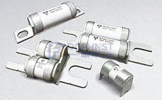
With an understanding of the short-circuit current magnitude, we now turn to selection. For high-voltage DC fuses used in energy storage battery clusters (most adopt ceramic arc-quenching housings, and are often referred to as high-voltage ceramic fuses in the industry), the following core parameters truly determine whether the selection is correct.
① Rated Voltage: Not lower than the maximum open-circuit voltage of the system, with engineering margin reserved
The rated voltage of the fuse shall not be lower than the maximum open-circuit voltage (Voc) of the system. In engineering practice, a safety margin of about 10% is usually reserved, and it can be increased to 15%–20% for harsh scenarios such as high altitude and extreme cold.
The reason is that the open-circuit voltage of the battery will rise under low-temperature fully charged conditions. When superimposed with the peak charging voltage, if the rated voltage of the fuse is only equal to the nominal voltage of the system, voltage breakdown may occur under extreme operating conditions, resulting in fuse failure.
Taking the current mainstream 1500V DC energy storage system as an example, the rated voltage of the fuse should be at least 1500V DC. A more rigorous approach is to verify its actual breaking performance at 1500V, rather than only referring to nominal parameters. Special attention should be paid: the breaking capacity of a fuse is strongly bound to its rated voltage. When the voltage is lower than the rated value, the breaking capacity will change accordingly, and parameters cannot be directly applied across different voltage levels.
② Breaking Capacity: Greater than the prospective short-circuit current of the system, with engineering margin reserved
Breaking capacity refers to the maximum fault current that a fuse can safely interrupt at its rated voltage. If the actual short-circuit current of the system exceeds the breaking capacity of the fuse, the arc cannot be extinguished during the melting process, causing risks of sustained arcing, explosion and even fire.
When calculating the prospective short-circuit current, it is not enough to only consider the internal resistance of the battery cell; the impedance of busbars, connectors and cables must also be included. For multi-cluster parallel systems, the total impedance after parallel connection and the current superposition effect must also be considered.
In engineering practice, the breaking capacity is usually set at no less than 1.2–1.5 times the calculated value as a margin. The breaking capacity of single-cluster fuses is mostly required to be above 30 kA, while the main fuses on the station-level busbar side generally require a breaking capacity of no less than 100 kA, and some high-specification products can reach 175 kA to 250 kA.
③ Time-Current Characteristic and I²t: Form hierarchical protection coordination with BMS and contactors
Some selection work only focuses on rated current and breaking capacity, and easily ignores the time-current characteristic (TCC curve) and let-through energy (I²t).
The overcurrent protection of energy storage systems is a hierarchical coordination mechanism: the BMS sends a disconnection command to the contactor after detecting overcurrent, and the contactor has an inherent action delay, while the fuse serves as the final protection line. If the fuse operates too slowly, the contactor may be ablated first; if it operates too fast, normal charge-discharge current fluctuations may cause false tripping.
Therefore, selection must verify the stepped coordination between the fuse’s TCC curve, BMS protection thresholds and contactor breaking time, ensuring the operation sequence is: BMS triggers first, contactor breaks next, and fuse provides final backup. Meanwhile, the I²t parameter must be matched to ensure that the let-through energy during fuse operation is lower than the withstand energy of contactors and cables, so as to realize full-link protection coordination.
Based on this demand, energy storage-specific fuses are usually marked as aBat or gBat categories, corresponding to the IEC 60269-7 / GB/T 13539.7 special standards for battery protection, which are different from ordinary gG and gL AC distribution products. Among them, aBat is for partial-range breaking (short-circuit protection only), and gBat is for full-range breaking (overload + short-circuit protection), which can be selected according to protection level requirements.
④ L/R Time Constant Adaptation: An implicit core requirement for DC scenarios
The inductance-resistance ratio (L/R time constant) of a DC loop is a key parameter that is easily overlooked in DC fuse selection. Inductance hinders current changes and stores magnetic energy at the same time, which will sustain the arc during fuse interruption and greatly increase the difficulty of arc quenching.
Breaking tests of conventional DC fuses are usually completed under the condition of L/R = 10–15 ms, but the L/R of long busbars and large loops in large energy storage power stations may exceed 20 ms or even higher. If the system L/R exceeds the fuse’s test conditions, derating of the rated voltage is required, or special products adapted to large time constants should be selected; otherwise, breaking failure may occur.
⑤ Bidirectional Current Adaptation
Energy storage systems have bidirectional current flow for charging and discharging, while some DC fuses are designed for unidirectional breaking (such as those dedicated to photovoltaic scenarios). During selection, it must be confirmed that the product supports bidirectional DC breaking to avoid protection failure under reverse current.
III. Common Selection Misconceptions
Misconception 1: The larger the rated current, the safer the fuse
This is the most common mistake in selection. Many people believe that increasing the rated current of the fuse can avoid false tripping caused by normal current fluctuations and thus improve safety. In fact, an excessively high rated current will prolong the operation time under fault conditions and narrow the protection range. After a fault occurs, the fuse response lags, and protection is not triggered even when the battery overheats.
A reasonable selection method is: the rated current is selected as 1.2–1.5 times the normal working current, and corrected with the ambient temperature derating coefficient. The higher the ambient temperature, the lower the actual current-carrying capacity of the fuse, so the rated current value needs to be adjusted accordingly.
Misconception 2: Direct application of AC fuses in DC circuits
This practice poses extremely high safety risks. In AC circuits, the current has a zero-crossing point in each cycle, and the arc can be extinguished naturally. In DC circuits, there is no zero-crossing point, and the arc will continue to burn once generated, resulting in essential differences in the requirements for fuse arc quenching capability.
Most AC fuses have a high nominal voltage, but there is no uniform conversion ratio for their DC breaking capacity. Some products even have no DC rated parameters and have no DC arc quenching capability at all. Applying AC fuses to DC energy storage circuits will leave significant safety hazards in the arc quenching link.
During selection, it must be confirmed that the product has clear DC rated voltage and DC breaking capacity parameters. It is not allowed to only refer to AC parameters, nor to convert DC capability from AC parameters by oneself.
Misconception 3: Breaking capacity compliance is sufficient, and package form has no impact
Package size not only affects installation space, but also directly relates to heat dissipation effect and arc quenching efficiency.
Under the premise of the same design structure and the same material, the larger the package size, the better the heat dissipation conditions, the more sufficient the arc quenching space, and the higher the actual operation reliability. However, large packages are limited by the system installation space.
The internal space of energy storage battery clusters is compact. Selection requires a balance between breaking capacity, rated current and package size, while paying attention to the impact of installation direction and contact resistance on heat dissipation.
IV. Reference for Mainstream High-Voltage Ceramic Fuse Solutions
Currently, the mature high-voltage DC fuse solutions on the market can be divided by protection level:
① 1500V DC station-level busbar side
This is the mainstream voltage level for current large-scale energy storage power stations, corresponding to the busbar loop after multiple clusters are connected in parallel. It has the highest requirement for breaking capacity, usually above 100 kA.
② 1000V / 1500V DC industrial and commercial energy storage cluster level
Industrial and commercial energy storage systems have a slightly lower voltage level and are more sensitive to cost and installation space.
③ Battery module-level protection
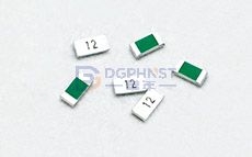
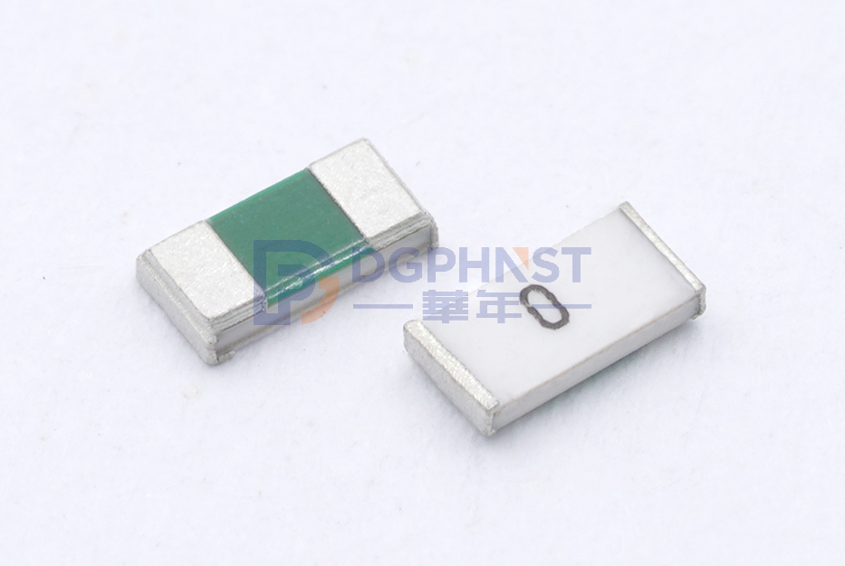
In addition to the main fuses at the battery cluster level, overcurrent protection is also required inside the battery modules. Fuses at this level are smaller in size and relatively lower in rated current, but have high requirements for response speed and consistency.
Such applications usually use miniature ceramic tube fuses or SMD fuses. Walter Electronics' ceramic tube fuse product line covers a range from milliampere level to tens of amperes, suitable for protection scenarios such as module-level and BMS sampling circuits. Its power fuse series can also cover the application requirements of cluster-level energy storage.
Closing Remarks
The overcurrent protection of energy storage battery clusters appears to be single-component selection on the surface, but is essentially a system-level protection coordination design.
Rated current is only a basic selection parameter. The core determinants of protection reliability include whether the breaking capacity is sufficient, whether the voltage adaptation is rigorous, whether the coordination of time characteristics and energy parameters with BMS and contactors is reasonable, and whether the time constant and bidirectional characteristics of DC scenarios are matched.
Fully verifying the above core parameters at the selection stage can effectively reduce solution iteration and verification costs in subsequent testing links.
If you are working on fuse selection for energy storage systems and are unsure how to calculate a certain parameter or whether a certain model is suitable for the current working condition, you can leave a message to Shunhai Technology, and we will provide selection suggestions combined with specific application scenarios.