——This article is edited by Shenzhen Shunhai Technology Co., Ltd., a high-power resistor distributor, and HuaNian Mall.
The wind direction of the energy storage industry is shifting: from speed competition in scale expansion to quality competition over the full lifecycle. In this adjustment, there is a type of component that is easily overlooked——low unit price, tiny proportion in the BOM, often represented as a block with two lines of parameters in schematics, yet directly determining the long-term reliability of the entire system. It is the high-power resistor.
1. PCS is the core of energy storage; resistors are critical protection devices
The Power Conversion System (PCS) is the energy dispatch hub of electrochemical energy storage systems: DC power from the battery side is inverted to AC via the PCS and connected to the grid; during charging, it is rectified back to DC. In high-power PCS units, thousands of amperes of current, thousands of volts of bus voltage, and tens of thousands of switching actions per second occur within the cabinet.
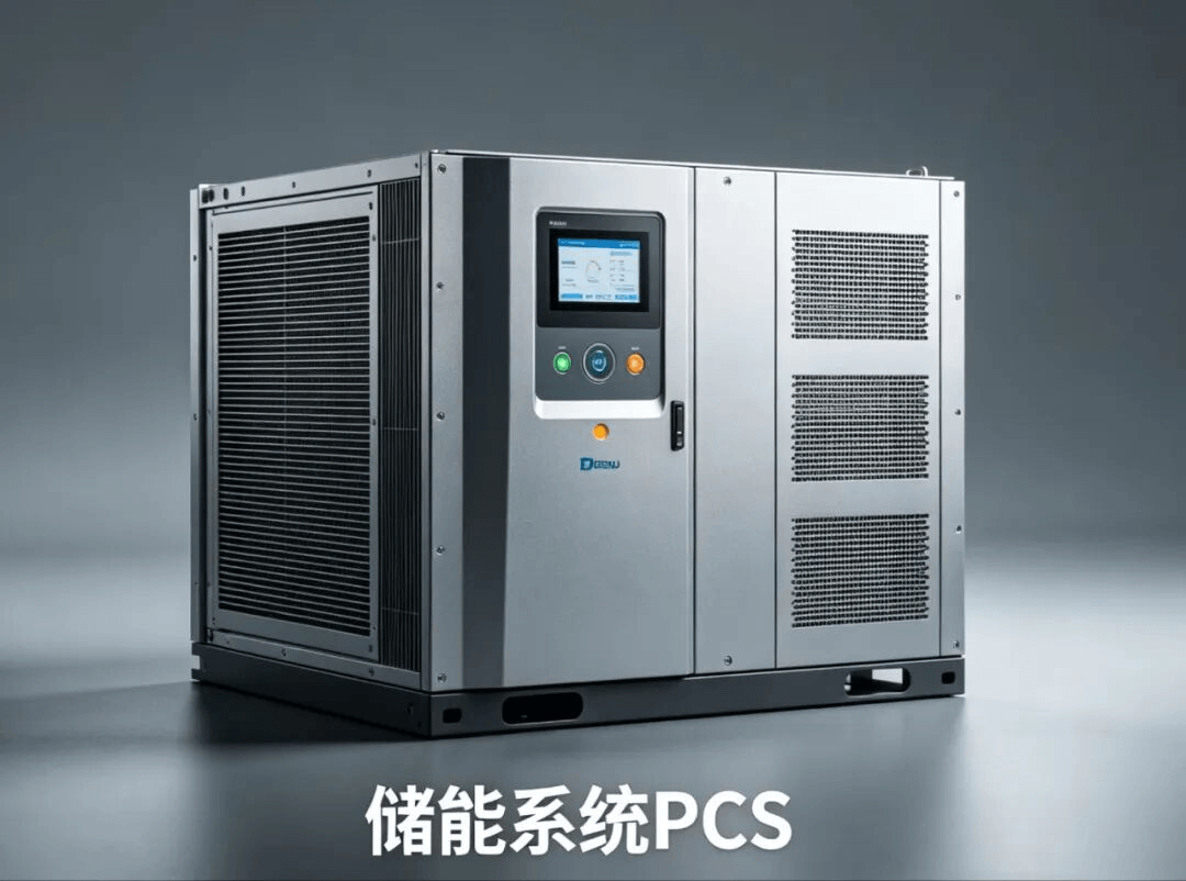
IGBT modules, bus capacitors, laminated busbars, and heat sinks determine efficiency, power density, and cost curves; however, what determines whether the equipment can operate stably until the end of its 10-year lifespan is often those "casually selected" small components.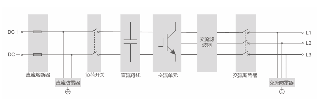
PCS Circuit Diagram
High-power resistors perform four functions in PCS: inrush current limiting at startup, discharging residual bus voltage at shutdown, absorbing IGBT turn-off voltage spikes, and sampling current/voltage signals. Each position seems inconspicuous, but failure in any one leads to: total system failure. Batch returns for repair.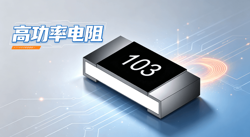
2. Analysis of Differential Selection for Four Major Functional Circuits
1. DC Bus Pre-charge Circuit
When the PCS starts up, thousands of microfarads of capacitors are parallel to the DC bus. The initial voltage is zero. If switched on directly, the inrush current can reach ten times or even dozens of times the rated value, far exceeding the surge tolerance of IGBTs and capacitors.
The pre-charge resistor acts as a series "current-limiting gate," restricting inrush current to a safe range. Once the capacitor charges close to the bus voltage, a contactor bypasses it. Its characteristic is that it does not work normally; when it acts, it faces extreme loads: it must withstand pulse energy several times the rated power within tens of milliseconds to seconds, without resistance drift, body cracking, or pin detachment.
2. DC Discharge (Bleed) Circuit
The discharge circuit rapidly releases stored energy from bus capacitors during fault shutdowns or maintenance; otherwise, residual voltage poses a threat to personal safety. Opposite to pre-charging, this involves short-duration continuous power consumption plus high-frequency cycling: a station-level system may start and stop several times a day. The resistor needs to work continuously for seconds to tens of seconds, requiring rapid heat dissipation. Heat dissipation capability and cycle fatigue resistance are primary requirements; resistance accuracy is secondary.
3. Snubber/Absorption Circuit
The snubber circuit addresses high-voltage spikes induced by high di/dt across stray inductances during IGBT turn-off. Lightly, it increases device stress; severely, it breaks down power devices. The core challenge here is high-frequency characteristics——switching frequencies can reach tens of kHz, and each turn-off is a microsecond-level pulse load.
High-frequency impedance stability, parasitic inductance, and pulse repetition tolerance are the three key parameters. Wire-wound resistors have high parasitic inductance; at high frequencies, their impedance deviates from nominal values and exacerbates oscillation. Thick-film resistors with insufficient pulse energy are prone to local ablation and resistance drift.
4. Sampling and Detection Circuit
Sampling resistors in detection circuits determine sampling linearity and temperature drift. Although the power load is small, the requirements are strictest: extremely low TCR, excellent long-term stability, and low thermoelectric EMF. If TCR is 50ppm/°C, a 60°C rise inside the cabinet causes a sampling deviation of 0.3%; since current loop control, SOC estimation, and overcurrent protection thresholds rely on this signal, deviations can lead to false trips or, worse, protection failure.
| Circuit Type | Core Operating Condition | Primary Metric | Typical Failure Mode |
| Pre-charge Circuit | Instantaneous Ultra-high Pulse | Pulse Energy Tolerance Resistance Stability |
Body Cracking, Resistance Jump |
| Bleed Circuit | Short-term Continuous Power + Frequent Cycling | Heat Dissipation Capability Fatigue Resistance |
Excessive Temperature Rise, Film Layer Aging |
| Snubber Circuit | High-frequency Repeated Spikes | High-frequency Characteristics Parasitic Inductance |
Local Ablation, Resistance Drift |
| Sampling Circuit | Low Power, High Precision | TCR Long-term Stability |
Inaccurate Sampling, False Protection Trips |
If the same resistor model is used for all four positions in a single BOM, it can be basically determined that at least three selections are unreasonable.
3. Three Common Selection Mistakes
Mistake 1: Looking Only at Nominal Power
Rated power is typically measured at 25°C, on specified heat sinks, under good natural convection. However, PCS cabinets are sealed, ambient temperatures can exceed 55°C, they are adjacent to heating busbars and inductors, and airflow is uneven——none of these conditions are met.
A resistor labeled 400W may actually dissipate only half or less of that power long-term. More commonly, if the calculated average bleed power is 200W, a 250W resistor is chosen thinking a 25% margin is safe——but theoretical values are average powers, while actual waveforms include periodic peaks, and nominal values are ratings under ideal cooling. Combined, the actual operating point has long exceeded limits.
The consequence is long-term overheating: no anomalies in the short term, resistance drift after six months, film layer cracking after one year, eventually leading to concentrated failures in the same batch and location.
Mistake 2: Compressing Component Costs, Weakening Pulse Tolerance Metrics
Pre-charge and snubber circuits must use specialized pulse power resistors. Standard power resistors' resistor bodies and terminal electrode connections are designed for steady-state power consumption.
After substitution, local film ablation, resistance drift, and micro-cracks appear after just a few startups. In extreme cases, surrounding components may ignite. The price difference is only a few yuan, but the costs of disassembly, transportation, downtime losses, trust erosion, and weeks of troubleshooting for a single batch return far exceed the price gap.
Mistake 3: Ignoring Environmental Adaptability
Scenarios like outdoor cabinets, coastal stations, and northwestern wind/sand areas involve stacked stresses: summer interior temperatures can reach 70°C, winter lows drop to -30°C, plus salt spray, high humidity, and dust. Civil-grade resistors' pin plating, packaging coatings, and potting processes cannot adapt.
Failure is gradual: pin oxidation increases contact resistance (often misdiagnosed as poor wiring), followed by coating moisture absorption and insulation degradation, finally leading to film-substrate delamination, with no warning throughout the process.
4. Five Core Metrics for Reliable Selection
First, calculate power margin and pulse capability separately. For continuous conditions like bleeding, recommend reserving more than 2x margin on rated power, converted to the actual ambient temperature inside the cabinet, rather than directly comparing against 25°C nominal values.
For pulse conditions, you must consult pulse power curves to clarify the relationship between single pulse energy and pulse width, derating curves for repetition frequency and allowable power, and calculate item by item using actual startup waveforms——under pulse conditions, energy tolerance is more critical than power parameters.
Second, consider temperature rise and heat dissipation paths from a structural perspective. Prioritize packages with short thermal paths: aluminum housing resistors use the outer shell as the heat sink surface, allowing direct mounting or addition of heatsinks; ceramic substrate thick-film resistors have low thermal resistance and good insulation. Also consider cabinet layout; insufficient spacing between multiple resistors causes additive radiant heat, requiring spacing or insulation boards for sensitive nearby components like electrolytic capacitors, optocouplers, and Hall sensors.
Third, select environmental tolerance levels based on the worst-case scenario. Recommend industrial grade as the baseline: operating temperature covering -40°C to +125°C, conformal coating treatment, and flame retardancy meeting UL94 V-0. For coastal projects, confirm salt spray grades separately; for humid regions, verify moisture-proof coatings and potting processes. These parameters are hard to expose during sampling and often manifest concentratedly after 2-3 years of field operation.
Fourth, focus on TCR and aging drift rate. Selection requires reverse-engineering the allowable resistance deviation over the full lifecycle, verifying if the device's TCR and aging curves can cover it. For sampling types, keep TCR within ±50ppm/°C; power types can relax this, but ensure resistance offset remains within tolerance under worst-case temperature rises.
Fifth, use certifications and mass application records to shorten verification cycles. New devices require temperature rise, pulse life, environmental, EMC, and whole-machine reliability verification from sample to mass production, taking at least six months. Therefore, prioritize checking for power electronics and energy storage industry certifications and mass application records in energy storage scenarios. Solutions that have run stably for years effectively complete field verification in advance.
5. Device Selection Plans for Typical Scenarios
- Main circuit pre-charge and bleed have the highest requirements for power and pulses. Choose high-power thick-film resistors covering 400W~800W, with high thermal conductivity ceramic substrates, strong pulse tolerance, and controllable temperature rise;
- Station-level high-power PCS can pair with aluminum-housed power resistors, offering direct heat dissipation paths, wide power coverage, and flexible installation.
- The core of sampling and snubber circuits is precision and high-frequency stability. Combine thick-film power resistors with high-precision alloy sampling resistors, with resistance accuracy of ±1%, TCR as low as ±50ppm/°C, and minimal parasitic parameters.
- Industrial environment standards, UL/RoHS certifications, and customized resistance/packaging support are practical bonuses;
Many field failures are not due to defective components but parameter mismatches with actual operating waveforms. Sample testing and joint debugging capabilities can significantly reduce such risks.
In Conclusion
The energy storage industry is moving from "competing on scale" to "competing on quality." Long-term system reliability is increasingly becoming manufacturers' core competitiveness.
Although small, high-power resistors are an important cornerstone for the safe and stable operation of PCS. By emphasizing passive component selection from the design stage, leaving sufficient margins based on actual conditions, and choosing the right solutions, companies can stand firm in fierce market competition through quality.