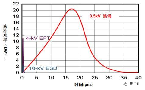
The reasons for generating surges are multifaceted, and surges are a type of spike pulse with high rising speed and short duration. Overvoltage in the power grid, switch ignition, reverse voltage, static electricity, and motor/power supply noise are all factors that cause surges. And surge protectors provide a simple, economical, and reliable protection method for power surge protection of electronic devices.
As is well known, electronic products often encounter unexpected voltage transients and surges during use, leading to damage to electronic products. The cause of damage is the burning or breakdown of semiconductor devices (including diodes, transistors, thyristors, and integrated circuits) in electronic products.
It is estimated that 75% of electronic product failures are caused by transients and surges. Voltage transients and surges are ubiquitous, and electricity grids, lightning strikes, explosions, and even walking on carpets can generate tens of thousands of volts of electrostatic induction voltage. These are all hidden and deadly killers of electronic products. Therefore, in order to improve the reliability of electronic products and the safety of the human body, it is necessary to take protective measures against voltage transients and surges.
Method 1: Ground the entire machine and system. The ground (common terminal) of the entire machine and system should be separated from the ground. Each subsystem in the entire machine and system should have an independent common terminal. When data or signals need to be transmitted between subsystems, the ground should be used as the reference level. The ground wire (surface) must be able to flow a large current, such as a few hundred amperes.
Method 2: Use voltage transient and surge protection devices in key parts of the entire machine and system (such as computer displays), so that voltage transient and surge can be bypassed to the subsystem ground and ground through the protection devices, thereby greatly reducing the transient voltage and surge amplitude entering the entire machine and system.
Method 3: For important and expensive equipment and systems, a combination of several voltage transient and surge protection devices is used to form a multi-level protection circuit.
Surge protectors provide a simple, economical, and reliable protection method for power surge protection of electronic devices. Through surge protection components (MOVs), surge energy is quickly transmitted to the ground during lightning induction and overvoltage operation, protecting the equipment from damage.
Protection methods for surges
(1) Parallel surge protectors are connected in parallel to the power supply line
Under normal circumstances, the varistor inside the lightning protection module is in a high resistance state. When the power grid is struck by lightning or momentary surge overvoltage occurs during switch operation, the lightning arrester responds within nanoseconds, and the varistor is in a low resistance state, quickly limiting the overvoltage to a very low amplitude.
When there is a prolonged continuous pulse or overvoltage in the circuit, the performance of the varistor deteriorates and generates heat to a certain extent, causing the thermal release mechanism to trip, avoiding the occurrence of fire and protecting the equipment.
(2) Series filtering type surge protector connected in series to the power supply line
To provide safe and clean power supply for valuable electronic devices, lightning waves not only have enormous energy, but also extremely steep voltage and current rise rates. Parallel surge protectors can only suppress the amplitude of lightning waves, but cannot change their sharp rising front. The series filtering type power surge protector is connected in series to the power supply line.
Under overvoltage conditions, MOV1 and MOV2 respond within nanoseconds to clamp the overvoltage; At the same time, the LC filter reduces the steep voltage and current increase rate of lightning waves by nearly 1000 times, and the residual voltage by 5 times, thereby protecting sensitive user equipment.
(3) Install voltage sensitive limiting components between phases and lines of power lines to limit surge overvoltage
The first method has a better protective effect on electrical equipment such as lighting, elevators, air conditioners, and motors that have a high level of impulse voltage resistance. But for modern electronic devices with high integration and compact structure, the actual protection effect is not so satisfactory. The reasons are as follows:
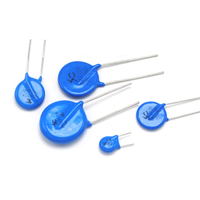
Taking the induction lightning protection of single-phase 220V AC power supply as an example, a common method is to install appropriate pressure-sensitive components between the zero and ground lines to absorb and limit the peak voltage generated by induction lightning strikes. The effectiveness of lightning protection in power lines depends entirely on the selection of parameters for varistors and the reliability of their operation.
The selection of pressure-sensitive limiting amplitude is based on the peak value of 310V of the mains power, plus 20% of the impact of grid fluctuations, 10% of device dispersion error, and 15% of reliability factors such as heating, moisture, and component aging caused by long-term operation compensation. The general value is between 470V and 510V. Various peak interference voltages such as induced lightning strikes are limited to 470V. For voltages below 470V, the pressure-sensitive device does not operate.
The power frequency withstand voltage of ordinary low-voltage electrical equipment (such as machine tools, elevators, lighting, air conditioning, etc.) is generally 1500V AC, and the instantaneous withstand voltage peak can reach 2500V or above, so a voltage of 470V is very safe. However, the working voltage of modern electronic devices composed of large-scale integrated circuits is generally between ± 5V and ± 15V, and the maximum withstand voltage value generally does not exceed 50V. Therefore, high-frequency peak voltages of less than 470V superimposed on the mains will be directly fed into the load. Through spatial coupling capacitors, the interlayer and electrode capacitance of transformers are disproportionately transmitted to the switching power supply or integrated circuit chip, which can cause faults.
Although high-frequency switching power supplies and electronic devices have corresponding measures to prevent peak interference, the protection effect is not ideal due to cost and volume limitations, as well as significant changes in the intensity and frequency spectrum of peak interference such as induced lightning strikes. This is still achieved in the ideal situation of pressure-sensitive limiting elements. In fact, due to the residual voltage of the pressure-sensitive elements and the influence of lead inductance, under strong induced lightning strikes, the actual limiting voltage peak may rise to above 800V to 1000V, posing a threat to subsequent electronic devices.
(4) Strengthen the protection effect of electronic equipment by connecting a super isolation transformer (also known as isolation method) in series between the power supply and load to isolate high-frequency peak interference, while also making the secondary equipotential connection easier to carry out
The isolation method mainly uses isolation transformers with shielding layers. Due to common mode interference being a relatively earth interference, it is mainly transmitted through the coupling capacitance between transformer windings. If a shielding layer is inserted between the primary and secondary layers and well grounded, the interference voltage can be diverted through the shielding layer, thereby reducing the interference voltage at the output end.
In theory, a transformer with a shielding layer can achieve a attenuation of about 60dB. But the effectiveness of isolation often depends on the process of the shielding layer. It is best to choose a 0.2mm thick copper plate, with a shielding layer added to the original and secondary edges. Usually, the shielding layer of the primary side is connected to the shielding layer of the secondary side through a capacitor, and then to the ground of the secondary side. The shielding layer of the original side can also be connected to the ground wire of the original side, and the shielding layer of the secondary side can be connected to the ground wire of the side. And the cross-sectional area of the grounding lead should also be larger. Using an isolation transformer with a shielding layer is a good method, but it has a larger volume.
This method has a limited market and few manufacturers due to the transformer's single function, relatively large volume and weight, inconvenient installation, and poor protection against mid - and low-frequency spikes and surges. So it is generally not used in non special occasions.
(5) Absorption method
The absorption method mainly uses absorbing devices to absorb the surge peak interference voltage. Absorbing devices all have a common characteristic of high impedance below the threshold voltage, and once the threshold voltage is exceeded, the impedance drops sharply, thus having a certain inhibitory effect on the peak voltage.
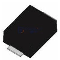
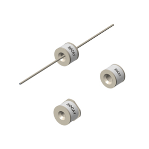
These types of absorbing devices mainly include varistors, gas discharge tubes, TVS tubes, solid discharge tubes, etc. Different absorbing devices also have their own limitations in suppressing peak voltage. If the current absorption capacity of the varistor is not large enough, the response speed of the gas amplification tube is slower.