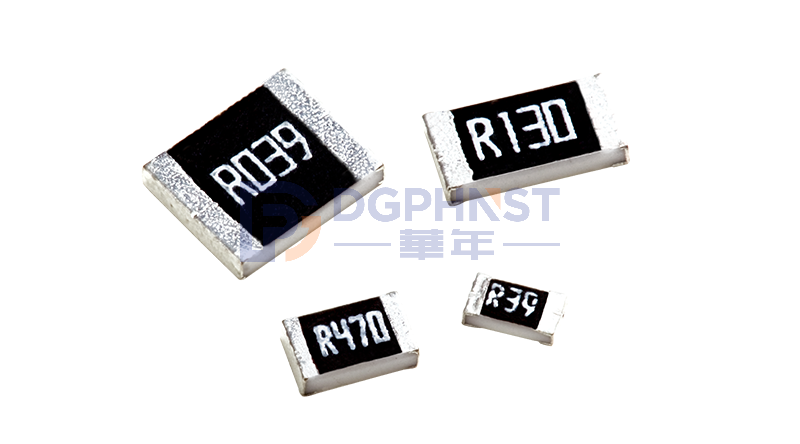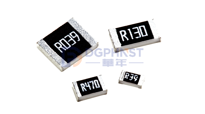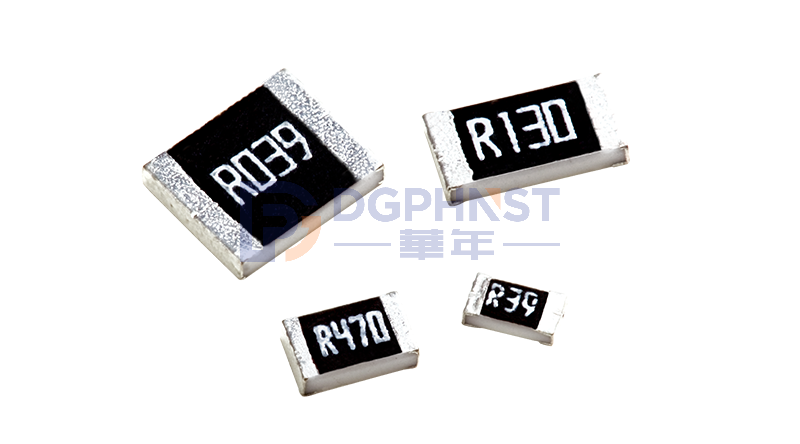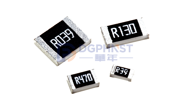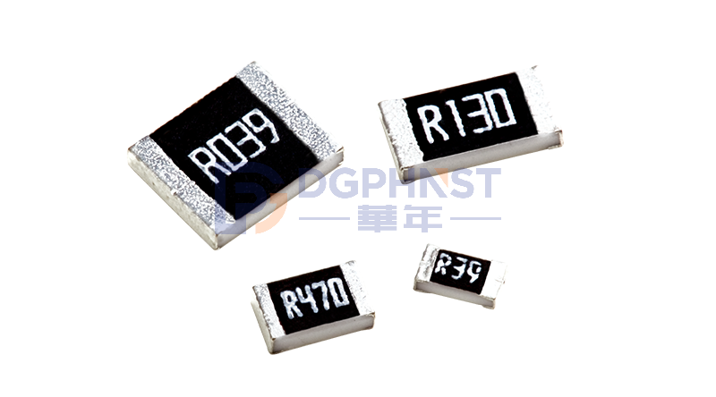
In various PCB boards of electronic devices, components are divided into two packaging forms: through-hole mounted components and surface mount components. As the basic core parts of circuit building, they are elements that realize circuit conduction, signal transmission, and power carrying, with differences in appearance, installation, welding, and application scenarios.
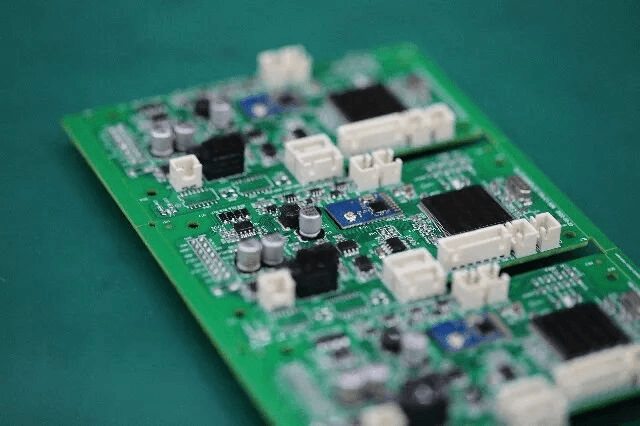
Shape and Structure
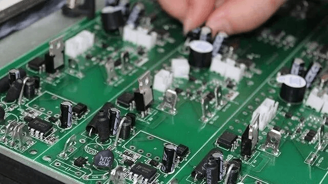
1. Through-hole mounted components, also known as through-hole components, have metal leads with a certain length. During production, these leads need to pass through pre-drilled plated-through holes on the PCB, and then be soldered and fixed on the back of the circuit board. The component body floats on the surface of the circuit board, with leads passing through the board, making the metal pins visible at the bottom of the board.
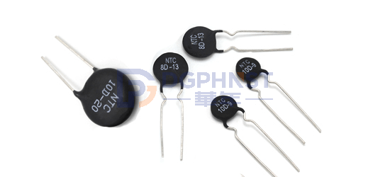
Through-hole component (through-hole thermistor)
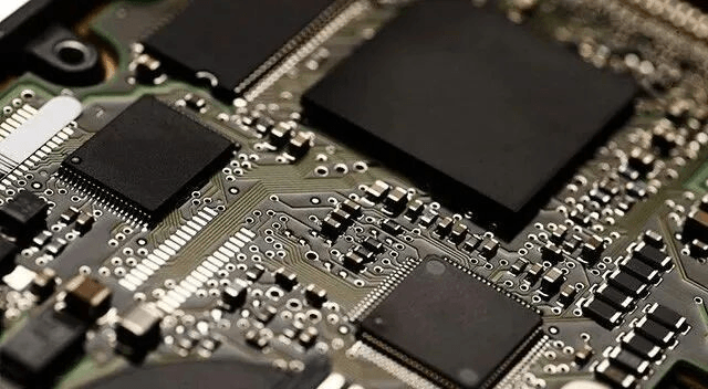
2. Surface mount components, also known as surface mount technology (SMT) components, do not have long metal leads but only have metal pads at the ends or around the component. These components are directly attached to the surface pads of the PCB without drilling through the board, lying completely flat on the board. Common examples include SMT resistors and capacitors with packages like 0402 and 0603, SMT diodes, SMT ICs, and SMT inductors. The smallest package size is just a few millimeters, almost invisible to the naked eye.
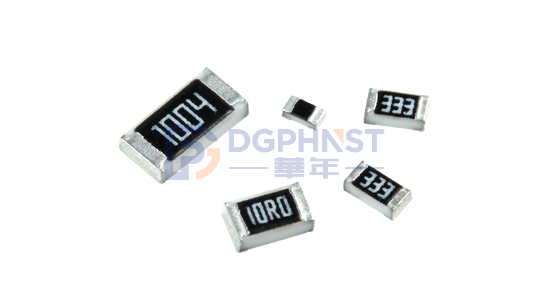
Surface mount component (thick film SMT resistor)
The most obvious difference between the two: lead structure. Through-hole components are fixed by long leads, while surface mount components are attached by flat pads.
Installation Method
1. Through-hole Packaging: Holes need to be drilled on the circuit board to accommodate the leads. They are usually installed using manual soldering or wave soldering. Due to the need for drilling, this method is more suitable for low-density and larger-sized circuits.
2. Surface Mount Packaging: Components are directly placed on the surface of the circuit board and installed using reflow soldering or manual soldering. This allows for high-density arrangement and is suitable for small-sized and high-performance electronic devices.
Assembly Production Process
1. Surface mount components are processed using fully automated SMT production lines, with a highly standardized and automated process: Solder paste printing → High-speed component placement → Reflow soldering cooling. A high-speed SMT machine can place tens of thousands of surface mount components per hour, with minimal human intervention, making it suitable for mass production. Reflow soldering completes the entire board's welding at once, resulting in uniform and stable solder joints, with high production consistency and extremely low batch production costs.
2. It is more difficult to automate through-hole components. Traditional processes mainly rely on manual insertion. Workers hold the components and insert their leads into the PCB through-holes, then complete the soldering via wave soldering. Even with automatic pin insertion machines, they can only handle simple through-hole components such as resistors and capacitors. Transformers, connectors, and large capacitors still rely on manual labor. Manual insertion is slow, costly, and prone to errors such as incorrect insertion, missing insertion, and bent leads, resulting in much higher defect rates than surface mount components in mass production.
3. Some products use a "surface mount + through-hole" hybrid process, where all small signal circuits on the motherboard are surface-mounted, while high-power and high-voltage components use through-hole mounting to balance size and performance. However, this requires two production lines, increasing production time and manufacturing costs.
Application Product Scenarios
1. Application scenarios of surface mount components: Compact, lightweight, high-frequency signals, and mass-produced consumer electronics: smartphones, smart wearables, notebooks, Bluetooth earphones, cameras, routers, graphics cards, small sensors, drone motherboards, etc.
2. Application scenarios of through-hole components: High-power, high-voltage, low-frequency circuits, fixed installation equipment, and products requiring easy maintenance: industrial control cabinets, high-power switching power supplies, charging piles, old appliances, audio amplifiers, terminal equipment, and large transformer PCBs.
3. Hybrid Process Scenarios
Most home appliance motherboards, TV power boards, and industrial control boards use a hybrid approach: the signal control part uses surface mount to reduce size, while the high-power power supply loop uses through-hole to ensure current carrying capacity and heat dissipation.
Mechanical Reliability and Shock Resistance
Consumer electronics such as mobile phones, smartwatches, and tablets are often in environments with vibration and drop, requiring high shock resistance for components. Surface mount components are fully adhered to the PCB with even stress distribution on the solder joints. Their thin and light packaging has a low center of gravity, making them less likely to fall off during drops and vibrations, with excellent shock resistance.
Through-hole components are fixed by leads that pass through the PCB. Although their theoretical tensile strength is stronger, long leads form a cantilever structure, which may cause metal fatigue at the junction of the lead and the plated-through hole under severe vibration and repeated movement, leading to lead breakage and false soldering. If through-hole components are widely used in car infotainment systems and outdoor portable instruments, long-term jolts may cause circuit failures. Industrial fixed control cabinets, which do not experience severe vibrations, make through-hole components more durable.
Soldering Methods
1. Soldering method for surface mount components: Place the component on the pad, apply the prepared SMT solder paste on the component surface and the pad, then use a 20W internal heating iron to heat the connection between the pad and the surface mount component (the temperature should be between 220~230°C). When the solder melts, remove the iron, and after the solder solidifies, the soldering is complete.
After soldering, use tweezers to check if the soldered surface mount component is loose. If there is no looseness, it indicates good soldering. If there is looseness, apply some solder paste again and follow the above steps to solder again.
2. Soldering method for through-hole components: When soldering all leads, add solder to the tip of the iron, coat all leads with flux to keep them moist. Touch the end of each lead with the tip of the iron until the solder flows into the lead. After soldering all leads, immerse the leads in flux to clean the solder and eliminate any short circuits or bridging.
Finally, use tweezers to check for cold solder joints. After inspection, remove the flux from the circuit board, and carefully wipe along the direction of the leads with an alcohol-soaked brush until the flux disappears.
Surface mount components, due to their automated mass production, high-density layout, and excellent shock resistance, have become the preferred choice for compact, lightweight, and mass-produced consumer electronics. Through-hole components, on the other hand, maintain their position in industrial equipment, high-power power supplies, and fixed industrial control equipment due to their strong current-carrying capability, voltage resistance, and convenient maintenance features.