Thyristors (thyristors) have multiple advantages, such as the ability to respond to low gate currents and switch from off state to high voltage, making them suitable for various applications. Including switches, rectifiers, regulators, protections, etc., thyristors are used for home appliance control, including lighting, temperature control, fan speed regulation, heating, and alarm activation. For industrial applications, thyristors are used to control motor speed, battery charging, and power conversion.
Next, we will summarize and explain some common application circuits of thyristors (thyristors), hoping to be helpful to everyone.
1、 Thyristor Application Circuit - As a Switch
Switching operation is one of the most important applications of thyristors (thyristors). Thyristors (thyristors) are commonly used as solid-state relays and have more advantages than electromagnetic relays or switches due to the absence of moving parts in them.
DC thyristor switch circuit
This simple "switch" thyristor trigger circuit uses thyristors as switches to control lights (as shown in the figure below), but it can also be used as switch control circuits for motors, heaters, or other similar DC loads.
The thyristor is forward biased and triggered to conduct by briefly closing the normally open "ON" button S1, which connects the gate terminal to the DC power supply through the gate resistor RG, allowing current to flow into the gate. If the value of RG is set too high relative to the power supply voltage, the thyristor may not trigger.
Once the circuit is turned on, it will self lock and remain on, even when the button is released, as long as the load current is greater than the locked current of the thyristor. The additional operation of the button has no effect on the circuit status of S1, as once "locked", the door will lose all control. The thyristor is now fully 'conductive', allowing the full load circuit current to flow forward through the device and return to battery power.

DC thyristor switch circuit
One of the main advantages of using thyristors as switches in DC circuits is their very high current gain. Thyristors are current operated devices because small gate currents can control much larger anode currents.
Usually includes a gate cathode resistor RGK to reduce the sensitivity of the gate and increase its dv/dt capability, thereby preventing device false triggering.
Due to the thyristor being locked to the "ON" state, the circuit can only be reset by interrupting the power supply and reducing the anode current below the minimum holding current (I H) value of the thyristor.
Open the normally closed "OFF" button, S2 disconnects the circuit, reducing the current flowing through the thyristor to zero, forcing it to "close" until another gate signal is applied again.
Replace DC thyristor switch circuit
However, one of the drawbacks of the above-mentioned DC thyristor circuit design is that the mechanical normally closed "OFF" switch S2 needs to be large enough to handle the circuit power flowing through the thyristor and lamp when the contacts are opened. If that's the case, we can replace the thyristor with a large mechanical switch.
One way to overcome this problem and reduce the need for larger and more robust "OFF" switches is to connect the switches in parallel with thyristors, as shown in the following figure.
The thyristor switch here receives the required terminal voltage and gate pulse signal as before, but the larger normally closed switch in the previous circuit has been replaced by a smaller normally open switch connected in parallel with the thyristor. The activation of switch S2 will immediately create a short circuit between the anode and cathode of the thyristor, preventing the device from conducting by reducing the holding current below its minimum value.
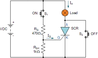
Replace DC thyristor switch circuit
Communication thyristor circuit
When connected to an AC power source, the behavior of the thyristor is different from the previous DC connection circuit. This is because the AC power supply periodically reverses polarity, so any thyristor used in the AC circuit will automatically reverse bias, causing it to "shut down" for half of each cycle, as shown in the AC thyristor circuit below.
The thyristor trigger circuit below is designed similarly to the DC SCR circuit, except that the additional "OFF" switch and diode D1 that prevents reverse bias from being applied to the gate are omitted.
During the positive half cycle of the sine waveform, the device is forward biased, but switch S1 is open, and zero gate current is applied to the thyristor and remains' off '. In the negative half cycle, the device is reverse biased and will remain 'off' regardless of the state of switch S1.
If switch S1 is closed, the thyristor will completely "turn off" at the beginning of each positive half cycle, but soon there will be enough positive trigger voltage, so there will be current on the gate to open the thyristor and turn on the light
The thyristor is now locked to "ON" during the positive half cycle. When the positive half cycle ends and the anode current is lower than the holding current value, the thyristor will automatically change to "OFF" again.
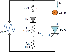
Communication thyristor circuit
During the next negative half cycle, the device is completely 'closed' until the next positive half cycle, when the process repeats itself and the thyristor conducts again, as long as the switch is closed.
Then in this case, the lamp will only receive half of the available power from the AC power source, as the thyristor acts like a rectifier diode and only conducts current during the positive half cycle when forward biased. The thyristor continues to provide half of the power to the lamp until the switch is turned on.
If switch S1 can be quickly turned on and off so that the thyristor receives its gate signal at the "peak" point (90 degrees) of each positive half cycle, the device will only conduct for the positive half cycle. In other words, conduction only occurs during half of the sine wave period, and this situation can result in the lamp receiving "a quarter" or a quarter of the total power obtained from the AC power source.
By accurately changing the timing relationship between the gate pulse and the positive half cycle, thyristors can provide any percentage of power required by the load, between 0% and 50%. Obviously, with this circuit configuration, it cannot provide more than 50% power to the lamp because it cannot conduct during the negative half cycle when it is reverse biased. Consider the following circuit.
2、 Application Circuit of Thyristor - Power Control Circuit
Thyristors can control the power transmitted to the load. It is usually necessary to change the power provided to the load according to load requirements, such as motor speed control and dimmer.
In this case, using traditional adjustable potentiometers to change power is not a reliable method because of the high power consumption. To reduce this power consumption in high-power circuits, thyristors are the best choice for power control devices.
Thyristor AC Power Control Circuit - Half Wave Phase Control
Phase control is the most common form of thyristor AC power control, and a basic AC phase control circuit can be constructed as shown in the following figure. The gate voltage of the thyristor here is obtained from the RC charging circuit through the trigger diode D1.
During the positive half cycle of thyristor forward bias, capacitor C charges with the AC power supply voltage through resistor R1. Only when the voltage at point A rises enough to trigger diode D1 to conduct and discharge the capacitor to the gate of the thyristor, will the gate be activated, thereby "conducting" it. The duration of the positive half cycle at the beginning of conduction is controlled by the RC time constant set by the variable resistor R1.
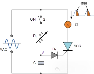
AC phase power control circuit
Increasing the value of R1 will delay the triggering voltage and current provided to the gate of the thyristor, which in turn will cause a delay in the device's conduction time. Therefore, the fraction of the half cycle of device conduction can be controlled between 0 and 180 degrees, which means that the average power consumption of the lamp can be adjusted. However, thyristors are unidirectional devices, so they can only provide up to 50% of the power in each positive half cycle.
There are multiple methods to achieve 100% full wave AC control using thyristors. One method is to include a single thyristor in a diode bridge rectifier circuit to convert AC power into unidirectional current through the thyristor, while a more common method is to use two thyristors in reverse parallel. A more practical approach is to use a single bidirectional thyristor, as this device can trigger in both directions and is therefore suitable for AC switch applications.
3、 Application Circuit of Thyristor - Half Wave Rectification
The following circuit shows a single-phase half wave rectification circuit using thyristors, with a diode connected in series with a variable resistor to the gate responsible for triggering the thyristors.

Application Circuit of Thyristor - Half Wave Rectification
During the negative half cycle of the input signal, the thyristor is reverse biased. Therefore, no current flows through the load.
During the negative half cycle of the input, the thyristor is positively biased. If the resistance is changed to apply the minimum trigger current to the gate, the thyristor will open. Therefore, the current begins to flow towards the load.
If the gate current is high, the power supply voltage when the thyristor is turned on will be lower. The angle at which the thyristor begins to conduct is called the trigger angle. For this rectifier circuit, the trigger angle can only vary within the positive half cycle.
Therefore, by changing the trigger angle or gate current (by changing the resistance in the circuit), the thyristor can conduct part or all of the positive half cycle, thereby changing the average power fed into the load.
4、 Application Circuit of Thyristor - Full Wave Rectification
In a full wave rectifier, both the positive and negative waves of the input power supply are rectified. Therefore, compared with half wave rectifiers, the average value of DC voltage is higher and the ripple content is also lower.
The following figure shows a full wave rectification circuit consisting of two thyristors connected to a center tap transformer.
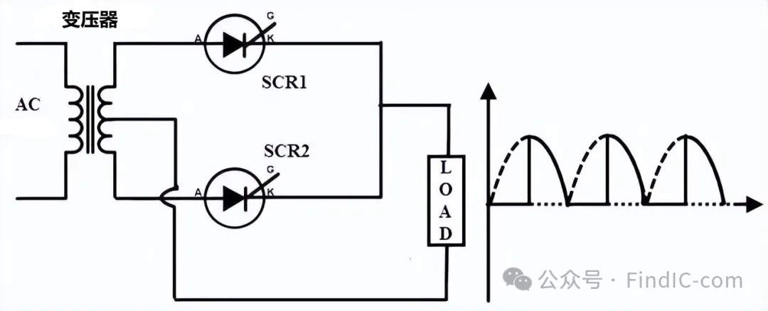
Application Circuit of Thyristor - Full Wave Rectification
During the positive half cycle of the input, SCR1 is forward biased and SCR2 is reverse biased. By applying an appropriate gate signal, SCR1 is turned on, so the load current begins to flow through it.
During the negative half cycle of the input, SCR2 is forward biased and SCR1 is reverse biased. When the gate is triggered, SCR2 is turned on, so the load current flows through SCR2.
Therefore, by changing the trigger current of SCR, the average power transmitted to the load will change.
5、 Application Circuit of Thyristor - Full Wave Bridge Rectification
In addition to using a center tap transformer, four SCR can also be used in a bridge configuration to achieve full wave rectification. During the positive half cycle of the input, SCR1 and SCR2 are in a conducting state. During the negative half week, SCR3 and SCR4 are in a conductive state. The conduction angle of each thyristor is adjusted by changing its respective gate current. Therefore, the output voltage at both ends of the load will change.
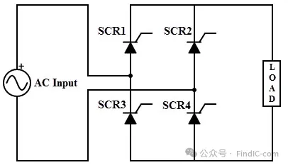
Application Circuit of Thyristor - Full Wave Bridge Rectification
In addition to the above, thyristors can also be applied to battery chargers, AC heater control, simple rain alarm circuits, anti-theft alarm circuits, etc.
The above is some explanation about the application circuit of thyristors. I hope it can be helpful to everyone. Please give me more guidance. If there is anything wrong, please feel free to correct it.
Recommended thyristor: CJ brand


