Many people can't distinguish between fusible resistors and fuses, knowing only that both will melt and protect when overcurrent occurs. However, they don't realize that from internal materials, circuit functions, melting speed, to suitable scenarios, these are entirely different components. Today we will comprehensively disassemble and explain all the differences between fusible resistors and fuses!
Basic Understanding: Core Definitions of the Two Components
1. Fuse (Fuse): A Single-Function Circuit Overload Protection Component
A single-function safety device with a pure metal filament structure inside, no resistance value, does not participate in circuit voltage division or current limiting. Its core function is to trigger a melt when a short circuit or large overcurrent occurs, directly cutting off the entire circuit. It belongs to a "one-time circuit protection".
2. Fusible Resistor (Fusible Resistor): A Combined Resistor + Fuse Component
A composite dual-functional component, essentially a surface-mount or through-hole resistor with a melting protection function, has a fixed resistance value. Under normal conditions, it acts as a voltage divider, current limiter, or sampling resistor. When an overload occurs, it quickly melts and cuts off the circuit, combining the electrical characteristics of a resistor with the protective features of a fuse.
Six Key Differences to Distinguish the Two Components
1. Essence
Fuse: A low-resistance conductor specifically designed for melting.
Fusible Resistor: A resistor with a certain resistance value.
2. Functional Attributes
Fuse: Only responsible for circuit protection against short circuits and large overcurrents. It does not consume voltage drop under normal power supply and does not participate in voltage division or current limiting in the circuit.
Fusible Resistor: Under normal operation, it performs the same role as a regular resistor, such as current limitation, voltage reduction, and load matching. When there is overcurrent or excessive temperature rise, the resistor material heats up and melts, cutting off the branch circuit for protection.
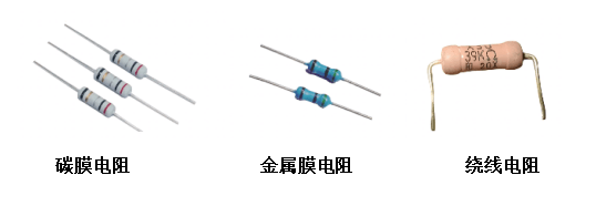
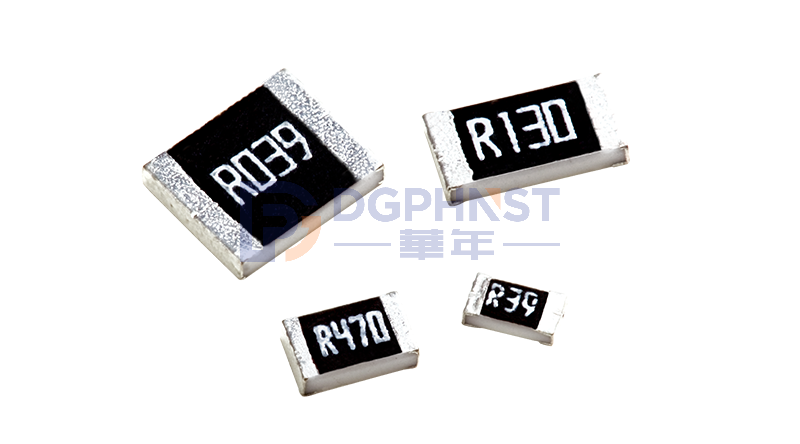
Common types and appearance of fusible resistors
3. Melting Trigger Logic
Fuse: Melts instantly within milliseconds, cutting off the circuit immediately upon short circuit, preventing strong currents from damaging downstream components. It is a one-time damage and cannot be restored after breaking.
Fusible Resistor: Melting speed is slower, relying on continuous high temperature to melt the resistor body. It is also a one-time damage and must be replaced entirely after melting.
4. Normal Circuit Function
Fuse: Connected in series with the main power line, it only serves as a path without changing the voltage or current parameters of the circuit.
Fusible Resistor: Connected in series with the branch circuit, it reduces the branch voltage and limits the branch current, optimizing the circuit load.
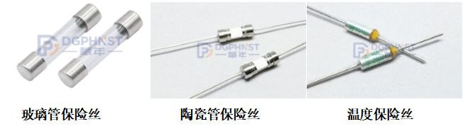
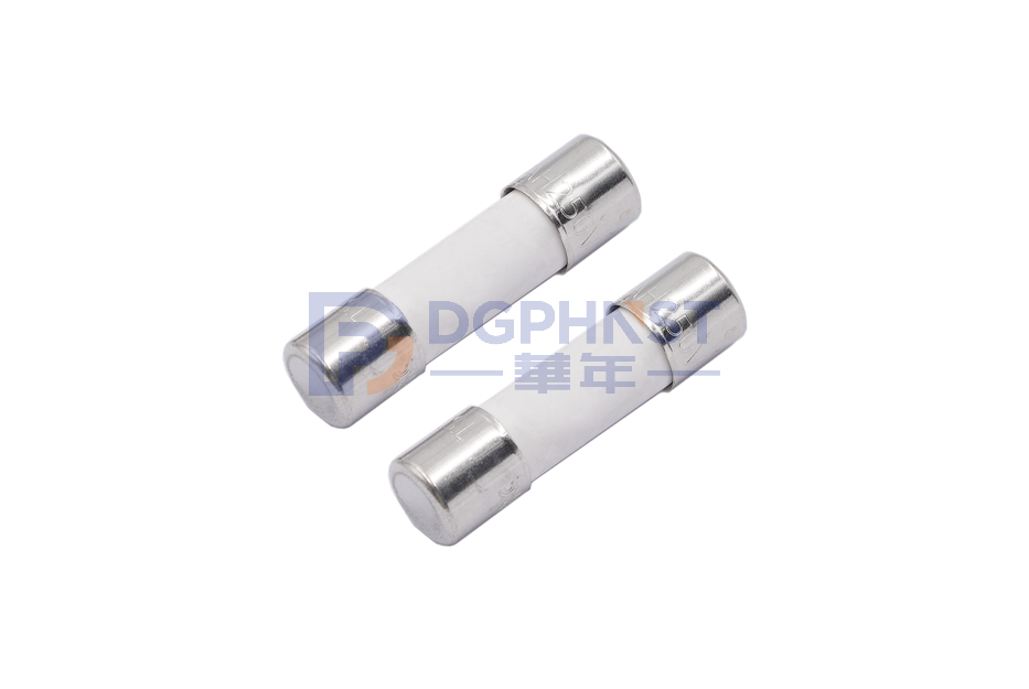
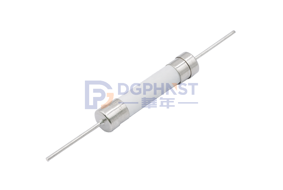
Common types and appearance of fuses
5. Damage Replacement & Cost
Fuse: Standardized specifications, low price, and simple replacement, with many standard models.
Fusible Resistor: Strong customization of resistance values, many model classifications, higher procurement costs, and replacement must match the original resistance value.
6. Tolerance Conditions and Lifespan
Fuse: Poor surge tolerance and weak impact resistance, suitable for main high-voltage, high-power power supply circuits.
Fusible Resistor: Strong high-temperature tolerance, good resistance to small fluctuations, and strong ability to withstand temperature rise, suitable for secondary branch circuits on PCB boards.
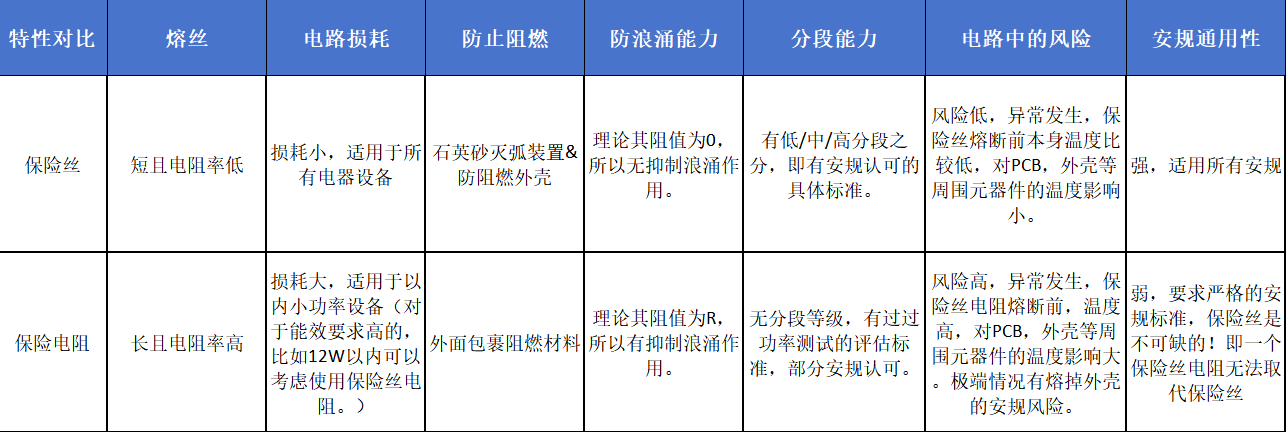
Comparison Table of Characteristics Between Fuses and Fusible Resistors:
Applicable Scenarios
1. Scenarios Where Fuses Are Preferred
AC input end of household appliances, input end of switch power supplies, lithium battery total circuit, industrial control main power supply, and high-power equipment master control circuits. The requirement is to cut off short-circuit current instantly and provide primary machine-level protection. Ordinary fuses, slow-blow/fast-blow fuses are the preferred choice.
2. Scenarios Where Fusible Resistors Are Preferred
Secondary power supply branches on PCB boards, LED driver circuits, small household appliance control boards, chip auxiliary power supplies, and load current-limiting circuits. If you need both resistor voltage reduction and current limitation and branch overcurrent protection, and want to save PCB space, directly choose fusible resistors.
Frequently Encountered Misconceptions in the Industry: Can They Be Interchanged?
First, the conclusion: Strictly prohibit unconditional substitution!
1. Replacing a fuse with a fusible resistor: The built-in resistance causes voltage drop to exceed standards, leading to insufficient power supply for downstream chips, resulting in black screens or system crashes.
2. Replacing a fusible resistor with a fuse: Losing the current-limiting and voltage-reducing function, the branch current directly exceeds the limit, causing mass burning of downstream chips and capacitors, losing branch current-limiting protection.
In Summary
In one sentence: Fuses are dedicated to protecting the circuit, while fusible resistors combine work and protection!
Although their appearance is similar and their functions overlap, their circuit roles and electrical parameters are completely different. Beginners should not judge by appearance when selecting.