Current sensing resistors frequently burn out even when the rated power calculation is sufficient and derating margins are adequate; in some scenarios, failure occurs immediately upon startup. Upgrading to larger packages or higher power ratings typically provides only temporary relief and does not resolve the issue fundamentally.
The core of the problem has never been as simple as "underestimating the power rating." However, repeatedly increasing power ratings and switching to larger packages fails to stop the recurring issues. In fact, in most cases, the critical bottleneck for resistor burnout is not insufficient rated power but rather an unestablished thermal dissipation path. Wide-terminal (long-terminal) structures are precisely the key solution to overcoming the heat dissipation dilemma in high-current sampling applications.
I. Why Do Your Current Sensing Resistors Keep Burning?
Many engineers focus solely on "average power consumption" during power calculations, overlooking the fundamental nature of sampling resistor failures, which often stem from three underestimated factors: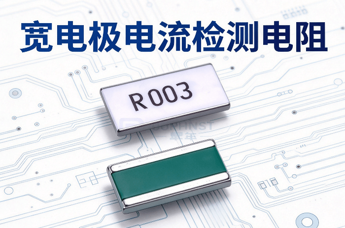
1. Localized Hotspots Due to Overheating, Not Overall Power Exceedance
In chip-type current sensing resistors, over 90% of the heat is conducted through the electrode pads to the PCB copper traces for dissipation. Traditional structures have narrow electrodes with small contact areas on the PCB, resulting in high thermal resistance. Heat concentrates within the resistor body and at the electrode connections, forming localized hotspots.
Even if the overall power does not reach the rated value, local temperatures may exceed the tolerance limits of the resistor material, leading to solder joint aging, resistor body cracking, resistance drift, or even burnout. This is particularly true for milliohm-level low-resistance resistors, where extremely high current densities cause current crowding effects at the electrode edges, further exacerbating localized heating. This explains why low-resistance values such as 2mΩ and 5mΩ are more prone to failure.
2. Transient Overload from Inrush Currents
Pulse currents generated during startup, load switching, short-circuit protection, and similar conditions are short in duration but carry significant energy. This process approximates an adiabatic condition, preventing timely heat dissipation. The temperature of the resistor body rises rapidly, potentially causing alloy layer melting or failure at the solder joints.
A typical phenomenon observed in the industry is that some resistors, despite having average power consumption at only 20% of their rated value, fail immediately upon first startup surge. The core reason is that the pulse energy exceeds the component's adiabatic withstand limit, which is not directly related to average power.
3. Cascading Failures Caused by High-Temperature Drift
Overheating of resistors not only reduces operational reliability but also causes Temperature Coefficient of Resistance (TCR) drift, leading to decreased accuracy in current sampling. This can trigger secondary faults such as control loop anomalies and false tripping of overcurrent protection. In stringent application scenarios like automotive and industrial control, excessive temperature drift may result in project certification failures and increased return-for-repair rates during mass production.
II. Wide Electrode Structure: What Problems Does It Solve?
Wide-electrode (also known as long-side electrode, wide-terminal, or side-electrode) current sensing resistors feature a core improvement: significantly widening the electrode pads at both ends without increasing the package outline dimensions, thereby optimizing the heat dissipation path structurally.
Its core advantages essentially represent comprehensive improvements across three dimensions:
1. Significant Reduction in Thermal Resistance, Doubling Heat Dissipation Efficiency
The wide-electrode structure directly increases the contact area between the resistor and the PCB pads, allowing more heat to be quickly conducted away via copper traces. Equivalent thermal resistance can be reduced by 30%~50%.
Taking the same package size as an example, traditional 2512 sampling resistors typically have a rated power of 2W. With the adoption of a wide-electrode structure, the rated power under the same package can increase to 3~5W. Under identical current conditions, the temperature rise of the resistor body can decrease by more than 40%, fundamentally solving overheating and burnout issues.
2. Uniform Current Distribution, Eliminating Localized Hotspots
In traditional narrow-electrode structures, current concentrates at the electrode edges for entry and exit, creating extremely high local current densities and forming hotspots. Wide electrodes allow current to distribute more uniformly across the entire cross-section of the resistor body, avoiding edge current crowding effects. Overall heating becomes more uniform, and peak temperatures are significantly reduced.
Additionally, wider electrodes reduce contact resistance, minimizing extra heat generation at solder joints. This improves mechanical reliability and electrical stability during long-term operation, while also ensuring higher SMT mounting yield rates.
3. Enhanced Surge Withstand Capability, Tolerating Transient Impacts
Wider electrodes and larger effective conductive cross-sections enable the resistor to withstand higher pulse energies. Surge withstand capability improves by more than 50% compared to traditional structures.
For scenarios such as startup surges and sudden load changes, Huade HTE series wide-electrode resistors can effectively absorb transient energy, preventing resistor failure caused by rapid temperature rises during adiabatic processes. This significantly reduces early failure rates during mass production.
III. Actual Test Comparison: How Large is the Performance Gap Under the Same Package?
Using the mainstream 2512 package as an example, we compare the core performance differences between traditional structures and wide-electrode structures:
| Performance Parameters | Traditional 2512 Current Sensing Resistor | Wide-Terminal 2512 Current Sensing Resistor |
| Rated Power at 70°C Ambient | 2W | 5W |
| Typical Thermal Resistance | ~15°C/W | 68°C/W |
| Body Temperature Rise at 2W Power Dissipation | ~30°C | 1216°C |
| Surge Withstand Capability | Basic Level | Improved by over 60% |
| Typical TCR Range | ±100~±200ppm/°C | ±50~±100ppm/°C |

As can be seen, with the same PCB footprint area, the wide-electrode structure achieves doubled power capability and halved temperature rise, while simultaneously improving precision and surge resistance. For projects where PCB space is limited and larger packages cannot be used, this is virtually the optimal thermal upgrade solution.
IV. Selection Considerations and Implementation Recommendations
When selecting wide-electrode current sensing resistors, in addition to resistance value, tolerance, and power rating, special attention should be paid to the following points:
- Prioritize products using metal clip/metal plate technology for lower TCR and better long-term stability;
- For automotive applications, AEC-Q200 certification must be confirmed to avoid compliance risks;
- During PCB design, maximize copper thickness and area under the electrode pads to fully leverage the heat dissipation advantages of the wide-electrode structure;
- For high-precision sampling scenarios, it is recommended to use Kelvin four-terminal connections to eliminate the effects of lead and solder joint resistance.
Conclusion
Returning to the initial question: Why do your current sensing resistors keep burning out? The answer is never simply "switching to a higher-power resistor." Local hot spots, transient surge overload, and cascading failures due to temperature drift—these three commonly overlooked dimensions are the true root causes of most failure cases.
Starting from the fundamental logic of heat dissipation paths and current distribution, the wide-electrode structure achieves increased power capacity, significantly reduced temperature rise, enhanced surge resistance, and optimized sampling accuracy without increasing the PCB footprint area. This serves as both a targeted solution for recurring resistor burnout issues and a selection trend for high-power-density, high-reliability electronic designs.
If you are facing challenges such as overheating and burnout of large-current sampling resistors or failing temperature rise tests, consider trying the HTE wide-electrode structure solution from WALTER. As an authorized distributor for WALTER, Shunhai Technology stocks the full series of HTE wide-electrode current sensing resistors and provides comprehensive selection support and sample services.