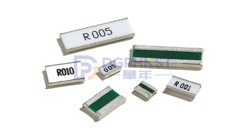
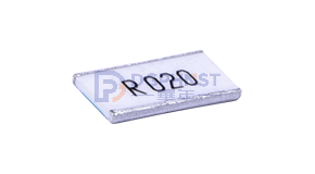
Walter Long Electrode Alloy Resistance HTE Series Selection Manual and Purchase Address: hnstshop.com/details/WALTER-HTE-M.html" target="_blank" >Click on the image to enter
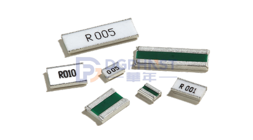
Long electrode alloy resistors refer to resistors made of metal materials from long sided solder pads, which are also commonly referred to as wide electrode resistors or side electrode resistors in the market. Long electrode alloy resistors mainly play a role in current detection in circuits, collecting real-time current conditions at both ends of the resistor and feeding them back to the control IC. Therefore, this type of current detection resistor is also called current detection resistor or sampling resistor or sampling resistor in the application process, because its resistance value is below 1 Ω (ohm), it is also called milliohm alloy resistor or low resistance value resistor. Next, we will introduce the long electrode alloy resistance HTE series of Suzhou Walter from the aspects of product characteristics, product Naming convention, model selection, resistance range table and test performance.
The Suzhou Huade Electronic Walter Long Electrode Alloy Resistance HTE series has the following advantages:
1. Wide range of volume options: 0805,1206,1508,2010,2512,3008,3015,3618,3921
2. Wide range of resistance options: 0.05mR~100mR
3. Wide range of power options: 1W~5W
4. High accuracy: △ ≤ 1%
5. Low temperature coefficient: TCR < 50ppm/℃
6. High frequency response: H < 5.0nH
7. Excellent low galvanic effect (EMF<0.5uV/℃)
8. How to use RoHS and REACH halogen-free standards
9. The anti welding layer complies with UL94-V0 level
10. Low inductance (<0.05uH 10MHz)
The Naming convention of Suzhou Huade Electronic Walter long electrode alloy resistance HTE series are as follows:
| HTE | 2512 | M | 3W0 | R001 | F | S |
| 1 | 2 | 3 | 4 | 5 | 6 | 7 |
1: Product series: HTE series, metal ceramic alloy current detection resistor, long electrode, two terminals, With lateral guide
2: Volume: 2512=6432=6.4 * 3.2mm
3: Material: M=Manganese copper alloy=MnCu alloy
4: Power: 3W0=3.0Watt
5: Resistance value: R001=0.001R=1mR
6: Accuracy: D=0.5%, F=1%
8: Product code: internal code or custom code
The selection parameters of Suzhou Huade Electronics Walter long electrode alloy resistance HTE series are shown in the table below:
|
Part Number |
Resistance Value (mΩ) |
Power Rating (Watt) |
Resistance Tolerance (%) |
TCR (ppm/℃) |
| HTE0805M1W0R | 1~9 | 1 | ±1%(F) | ±100ppm |
| 10~100 | 1 | ±0.5%(D)±1%(F) | ±50ppm | |
| HTE1206M1W50R | 1~9 | 1.5 | ±1%(F) | ±100ppm |
| 10~100 | 1.5 | ±0.5%(D)±1%(F) | ±50ppm | |
| HTE1508M2W0R | 1~9 | 2 | ±1%(F) | ±100ppm |
| 10~100 | 2 | ±0.5%(D)±1%(F) | ±50ppm | |
| HTE2010M2W0R | 0.5 | 2 | ±1%(F) | ±150ppm |
| 1~9 | 2 | ±1%(F) | ±100ppm | |
| 10~100 | 2 | ±0.5%(D)±1%(F) | ±50ppm | |
| HTE2512M3W0R | 1~9 | 3 | ±1%(F) | ±100ppm |
| 10~100 | 3 | ±0.5%(D)±1%(F) | ±50ppm | |
| HTE3008M3W0R | 1~9 | 3 | ±1%(F) | ±100ppm |
| 10~100 | 3 | ±0.5%(D)±1%(F) | ±50ppm | |
| HTC3015M4W0R | 1~9 | 4 | ±1%(F) | ±100ppm |
| 10~100 | 4 | ±0.5%(D)±1%(F) | ±50ppm | |
| HTE3618M4W0R | 1~9 | 4 | ±1%(F) | ±100ppm |
| 10~100 | 4 | ±0.5%(D)±1%(F) | ±50ppm | |
| HTE3618M5W0R | 1~9 | 4 | ±1%(F) | ±100ppm |
| 10~100 | 4 | ±0.5%(D)±1%(F) | ±50ppm |
Walter Long Electrode Alloy Resistance HTE Series Functional Characteristics:
|
Parameter |
Conditions |
Consent Standard |
|
Short time over load |
Power=2.5*Pr ; T=25±2℃ ; t=5s |
± (1.0%+0.5mΩ) IEC60115-1 4.13
|
|
High temp. exposure |
T=+155±2℃; t=1,000hrs |
± (1.0%+0.5mΩ) IEC60115-1 4.25 |
|
Low temp. load life |
T=-55±2℃ ; t=1,000hrs |
± (1.0%+0.5mΩ) IEC60115-1 4.25 |
|
Moisture load life |
Vtest=Vmax, ton=90min,toff=30min, T=60±2℃,RH=95%,1,000hrs |
± (2.0%+0.5mΩ) IEC60115-1 4.25 |
|
Thermal shock |
[-55℃ 30min→ R.T. 3min→ +150℃ 30min→ R.T. 3min] by 100 Continuous Cycles |
± (1.0%+0.5mΩ) IEC60115-1 4.19 |
|
Load life at 70℃ |
Vtest=Vmax ; T=70±2℃ ; t=90min On t=30min Off; 1,000hrs |
± (2.0%+0.5mΩ) IEC60115-1 4.25 |
|
Solderability |
Dipped into solder at 245±5℃ for 3±1s |
The covered area >95% IEC60115-1 4.17 |
|
Resistance to solder heat |
20±1s at 275±5℃ |
±(1%+0.5mΩ) IEC60115-1 4.18 |
|
Substrate bending |
Span between fulcrums: 90mm; Bend width: 2mm; Test board: Glass-epoxy board, Thickness=1.6mm by 10 continuous cycles |
±(1%+0.5mΩ) IEC60115-1 4.33 |
|
Mechanical shock |
a=100G for 11ms, 5 Pulse |
±(1%+0.5mΩ) IEC60115-1 4.21 |


